Use of the Multi-layer Faraday Collector as a Convenient Transferable Standard for Proton Range and Beam Energy
Background and Aims
It is highly desirable that proton therapy facilities plan and deliver treatments based on consistent assumptions and datasets. The control of longitudinal range, as determined by beam kinetic energy, is a key concern. Clinicians in fact have no direct interest in beam energy as such; their concern is the dose curve in water resulting from a particular machine setting. This is the information used by the treatment planning system. Measurement of the dose curve requires a water tank and ionization chamber system which requires some expertise to use, and is not well-suited for transportation between facilities.
The multi-layer Faraday collector (MLFC) developed by Gottschalk [1] is by comparison compact and robust. Rather than measuring the depth-dose curve, it measures the charge deposition as a function of depth, which is also monotonic with beam energy. We describe a scheme now underway to establish a population of well-characterised and cross-calibrated MLFCs which can be provided to different facilities. A simple protocol will gather the cross-reference data in a few minutes. Monte-Carlo calculations using Topas [2,3], are used to illustrate the relationship between MLFC response and range in water, and to allow the device to make absolute beam energy and energy spread measurements.
In this presentation we show measured data that support the use of the MLFC as a stable and convenient standard for comparing the performance of a proton therapy system over time.
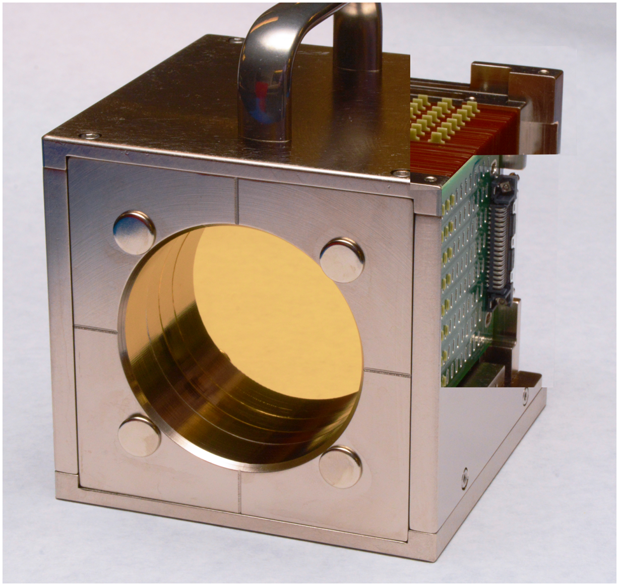
MLFC assembly cut away to show 128 layers of OFHC copper and readout connection boards. The device weighs 5.6 kg and is about 12 cm in all axes. It becomes activated after a period of use, but the radiation typically decays sufficiently overnight such that it can be transported.
MLFC spectra related to dose distribution in water
The MLFC measures stopping of ions in a material (pure copper for example) that is highly stable and consistent, but is not directly interesting for proton therapy. However we can relate the MLFC peak position measured in layers to the dose/depth curve in water, and therefore establish the MLFC as a convenient and precise transfer standard.
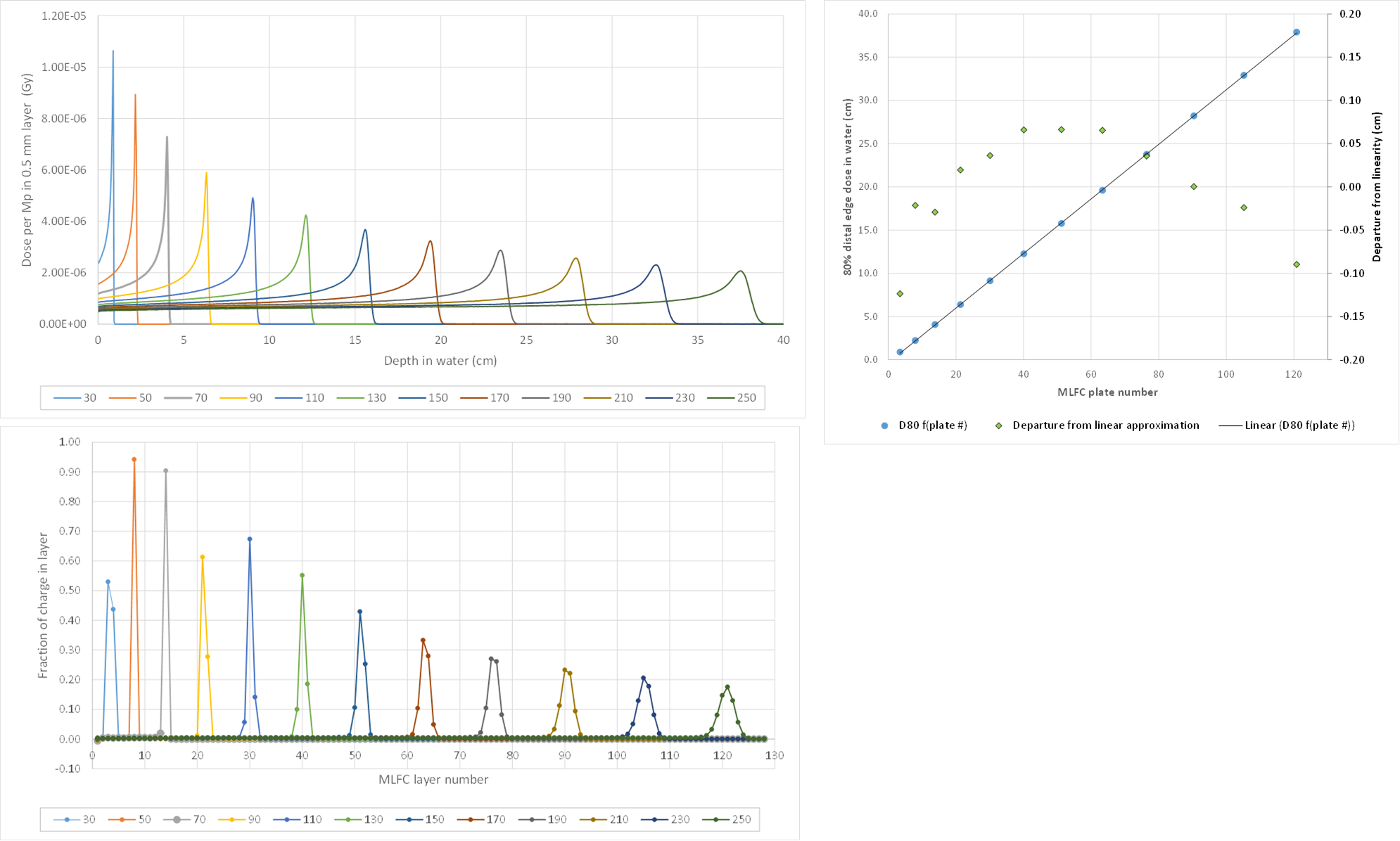
Topas Monte-Carlo calculations of dose-depth in water and charge deposited in a 128-layer MLFC as a function of proton beam energy. The plot above shows the linear relationship between the 80% distal edge depth in water and the fitted centroid in the MLFC. For this MLFC geometry, 80% depth (cm) = 0.316*layer# - 0.331
Beam energy consistency testing
It is not necessary to have the MLFC calibrated to use it for the basic task of doing QA testing of the energy reproducibility of a particular system. The device simply has to be stable in the long term, which is a reasonable assumption given its monolithic construction and lack of temperature or pressure dependence.
The results shown below were taken two weeks apart at the Francis H Burr Proton Therapy Center at Massachusetts General Hospital. The table shows the fitted layer number of the MLFC spectrum peak at five isocenter energies delivered by the accelerator. Two devices (#8 and #9) with nominally identical build were tested on the first date, and one of them was also tested with two different sets of readout electronics. Two weeks later unit #9 was tested again with the same beam energies.

On the later date some errors were being observed in the energy selector field readback of the machine, but the reproducibility of the MLFC result provided good confidence that the beam energy was not in fact changed by any significant amount.
Absolute beam energy accuracy
In principle the MLFC allows an ab-initio direct measurement of proton energy, using only the documented stopping power in the material and careful control of the construction. The following results compare measured spectra taken on two MLFCs for proton energies 70 to 250 MeV taken on a synchrotron system, with a Topas calculation for the nominal MLFC geometry and corresponding energies after degradation in the nozzle and air path.
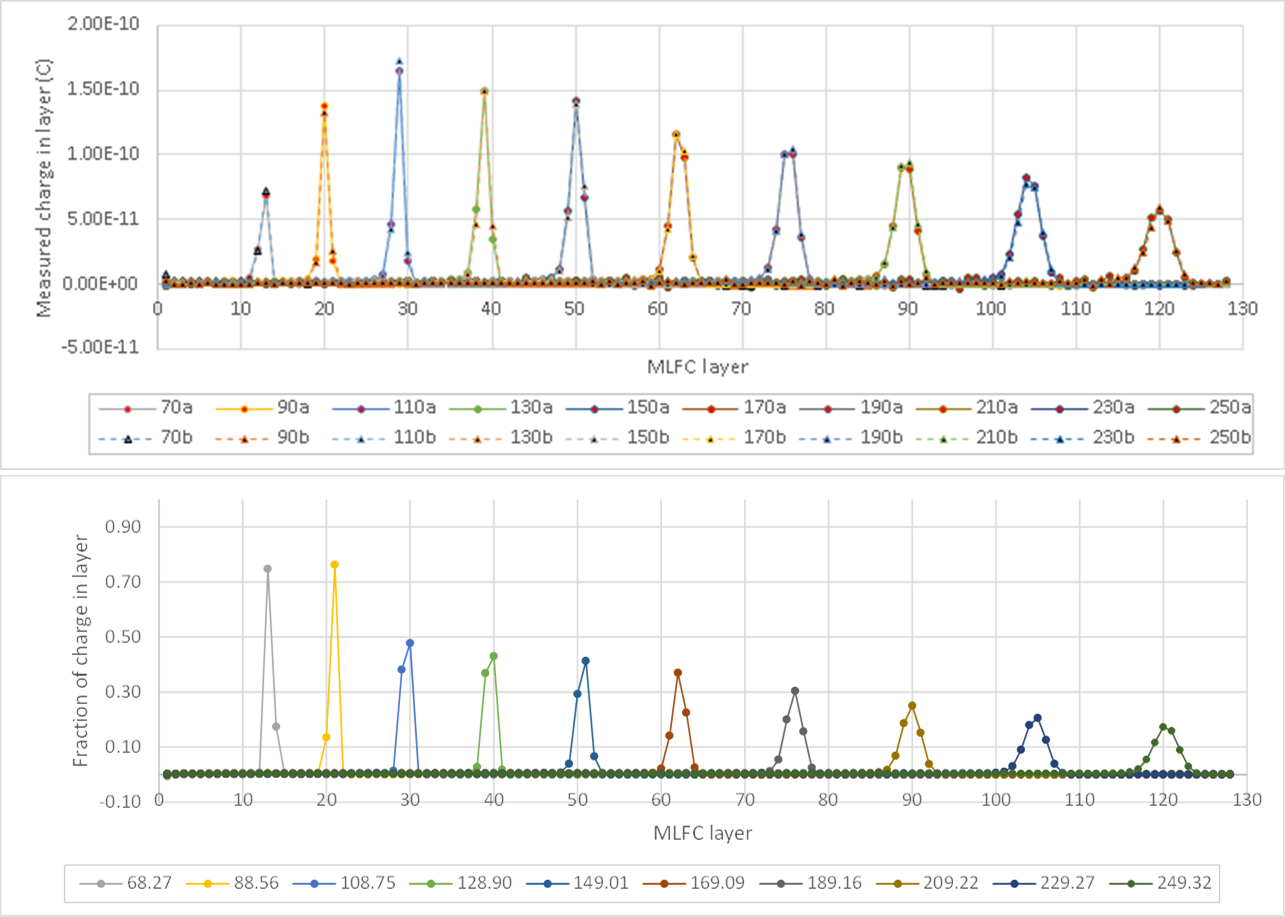
Comparison of measured (top) and calculated (bottom) MLFC spectra for ten beam energies delivered to isocenter by a synchrotron system. The peak positions for two different MLFC samples overlay nearly perfectly.
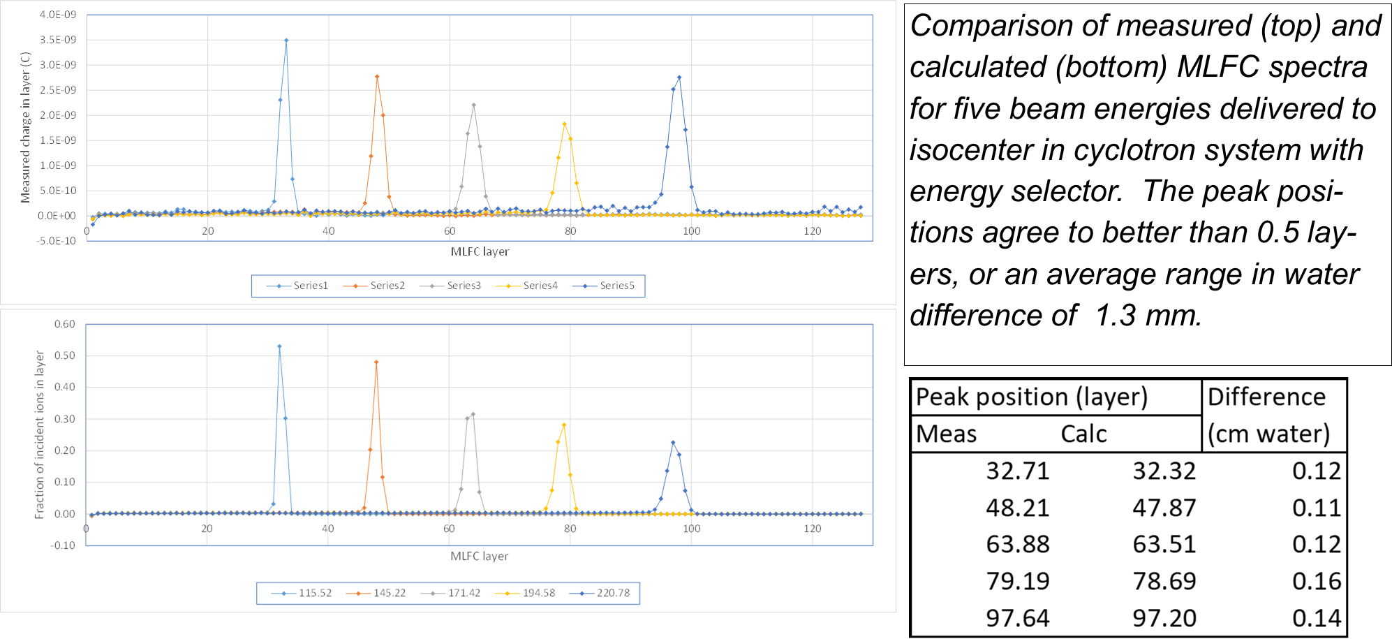
The calculations differ by 0.5 layers on average across the energies, with no difference greater than 0.7 layers. For better absolute accuracy, we can model the actual measured weights and dimensions of a specific MLFC. The following results compare measured MLFC spectra taken on a cyclotron system with a customized Topas calculation for the actual MLFC geometry. The measurements took a few seconds per energy, considerably less time than the Monte-Carlo calculations.
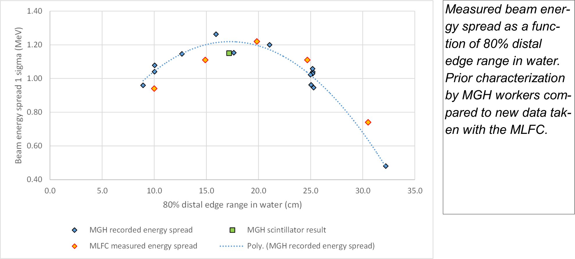
Energy spread determination
The peak widths in the MLFC spectrum are the convolution of the natural longitudinal range straggling and the actual energy spread of the beam. A Monte-Carlo calculation with a monoenergetic beam is used to provide the longitudinal straggling component, then the energy spread values in the measured data can be extracted by assuming they are uncorrelated with the straggling and add in quadrature. The spread in the MGH system as a function of energy had previously been characterized using the Golden dataset [4] and spectrometric measurements [5]. The MLFC result compared very well in both absolute value and in the overall shape of the curve.
Further work
A set of cross-related MLFCs will now be made available to various centers to allow beam energies and ranges in water to be compared using a convenient transfer device.
A lower-energy version (50 to 125 MeV protons) has been built and is being tested. This gives better resolution at these lower energies, and is primarily intended to assist system builders as they develop new machines.
Acknowledgements
We are grateful to Dr Ben Clasie, Ethan Cascio, Bob Brett and Dr Jay Flanz for data taken on the MGH system, and to Dave Dickey, Dr Bijan Arjomandy, Kevin VanSickle and Valeri Kozlyuk for data taken at the McLaren Proton Center.
References
[1] B. Gottschalk, http://users.physics.harvard.edu/~gottschalk/
[2] J. Perl, J. Shin, J. Schumann, B. Faddegon, H. Paganetti, Med. Phys. 39(11) (2012) 6818
[3] S.Agostinelli et al, Nucl.Instr. & Meth. 506.3 (2003) 250
[4] B.Clasie et al, Phys. Med. Biol. 57.5 (2012) 1147
[5] E.Cascio, private communication (2016)