A Large-area High Resolution Imaging Detector System for PBS Quality Assurance
Background
The beam tracking ionization chambers in a pencil-beam scanning system measure the beam properties typically around 50 cm before the isocenter. The results are projected to the isocenter plane to allow direct comparison with treatment maps. Clearly it is desirable to make measurements at the isocenter, and QA protocols typically require the use of an independent sensor at isocenter to validate the results from the built-in ionization chambers. For PBS beam qualification, this should be a device that can measure the position, shape and intensity of the beam spots at rates sufficient to follow a real irradiation spot sequence. The technical challenge is to produce a device that has large area, covering the extents of all or most irradiation maps while simultaneously providing sufficient spatial resolution for beam spots which may be as small as 3 mm sigma. 2-D (pixilated) readout is preferable because it is able to expose some undesirable beam shapes that are invisible to strip-readout chambers [1].
Various groups and suppliers have produced pixilated ionization chambers for particle therapy [2-7]. In order to keep the number of parallel readout channels to a reasonable number (1024 is a typical maximum), these must either be of limited area but good spatial resolution, or large area but comparatively poor spatial resolution.
In this work we have built and operated a prototype of an ionization chamber that is specifically intended for pencil beam scanning and combines high spatial resolution with large sensitive area without needing an excessive number of readout channels.
Method
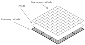
The means to achieve the combination of high resolution with large area at reasonable cost is to integrate two ionization chamber layers into a single unit. The first layer has a thin film readout electrode which tiles the whole area with relatively large pixels, for example 1024 pixels at 7.8 mm pitch to give a 25 by 25 cm square, read out by 1024 electrometer channels. This is the coarse resolution array. The second layer has 1.95 mm pitch pixels in a 6.25 cm square pattern which make up a sub-array. This sub-array is repeated over the same area as the coarse array with corresponding pixels of the sub-arrays connected in parallel to a further 1024 electrometer channels. This is the fine resolution array. If each pixel in the fine array had been connected to an individual channel, there would have been a total 16,384 channels, whereas this design only requires 2048 channels.
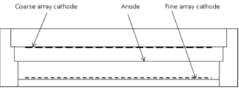
Dual resolution ionization chamber concept. The coarse readout electrode covers the whole sensing area with about 1000 relatively large pixels. The fine readout cathode has a much finer pattern with about 16,000 pixels total. A sub-array in the fine pattern is repeated over the sensitive area and corresponding pixels in each sub-array are connected to one electrometer input.
The raw signals from the fine resolution array are ambiguous. As a beam spot moves across the sensor, it “wraps around” on the fine array output and appears to repeatedly cross the field of view. However by using the unambiguous beam position provided by the coarse array, it is always possible to assign a beam centroid position on the fine array, and then reconstruct the beam spot without ambiguity.
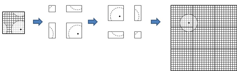
A beam spot is measured on the fine array in high resolution, It is reconstructed and located in physical space using the provisional centroid obtained from the coarse array.
There is no dead space in the ionization chamber readout, so an integral of the signals on either array will be related to the beam intensity in the usual way.
The only constraint of this approach is that to allow perfect reconstruction, the beam extents should not exceed the dimensions of the sub-arrays. Any violations of this are of course apparent from the coarse array data. The method is specific to pencil beam scanning, but this is precisely where the improved resolution is needed.
To test the concept, we built a prototype that could be read with 256 electrometer channels provided by two I128 electrometers [8]. The coarse array comprised an 11 by 11 array of pixels with 12 mm pitch laser-etched onto 25 µm stretched aluminized polyimide film. The anode was a two-sided stretched aluminized polyimide film, and the fine array was a circuit board with 16 sub-arrays of 3 mm pitch pixels. The active gaps were 10 mm of dry air.
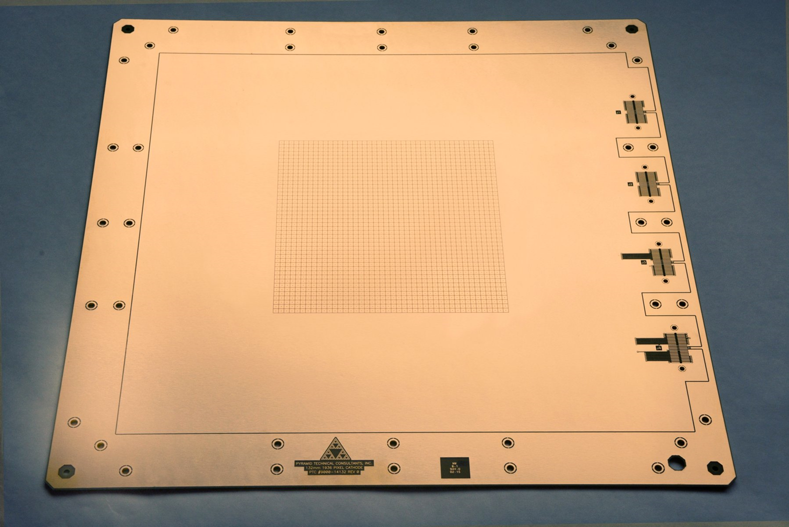
Fine resolution readout electrode used for the proof of principle prototype of the detector system. The pixel pattern is a four by four array of 11 by 11 sub-arrays of 3 mm pitch pixels. In the full implementation the patterning will cover the whole area and have finer pitch.
Results
The prototype sensor was tested with a collimated 40 kV X-ray source that could be moved to put a beam spot at any position in the sensing area. Software was written to do the reconstruction every millisecond. We moved the beam spot around and confirmed visually that the reconstruction was always made without artifacts. The contrast between the view of the beam spot provided by the coarse and fine arrays was quite dramatic.
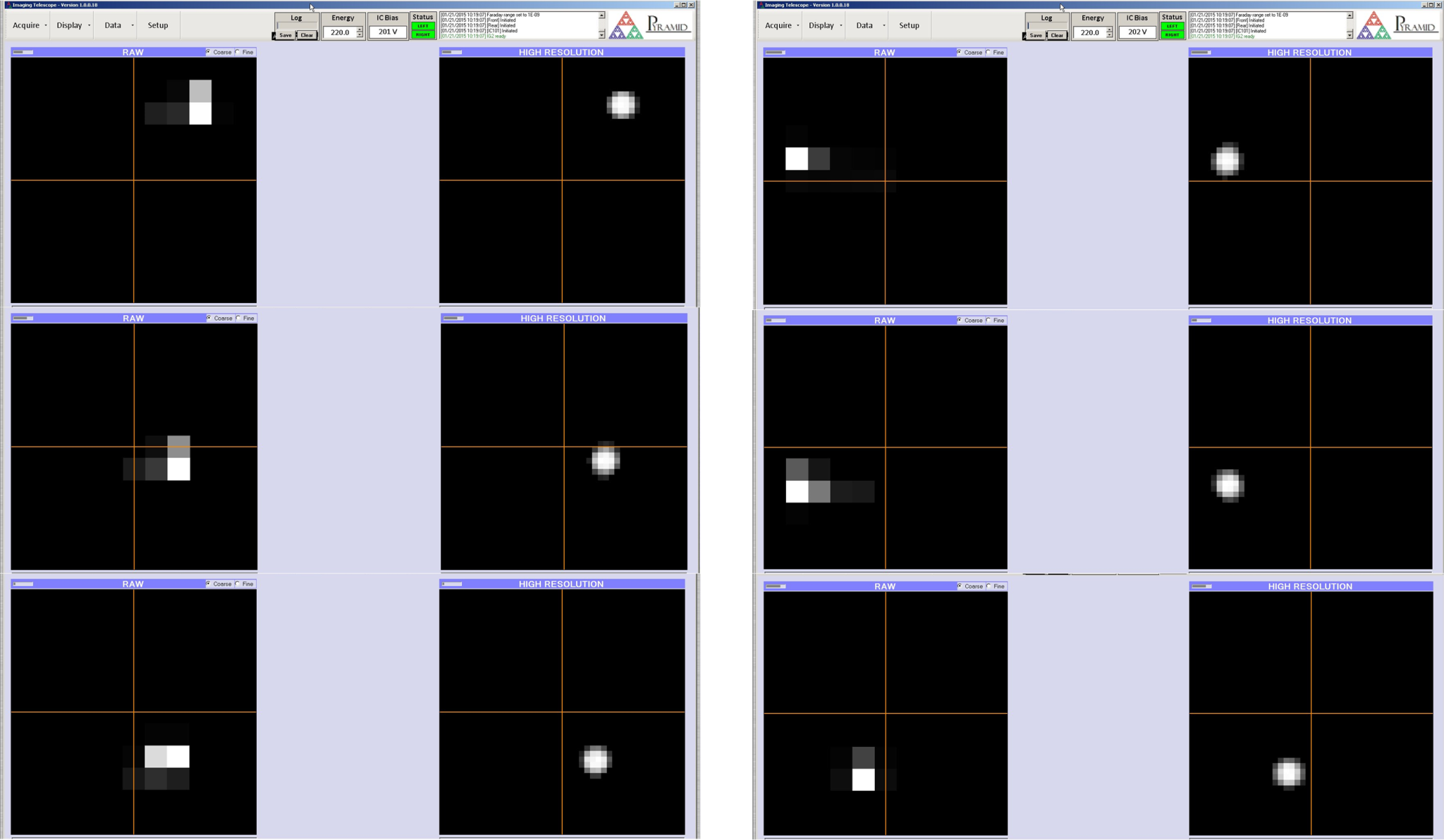
Six screen shots showing the beam moving across the sensor. Coarse array data on the left (hidden in some screenshots) and reconstructed fine array data on the right.
Further work
The next step will be to make a full area system with 2 mm pixel pitch on the fine array. This will require 2048 readout channels. This is possible with existing electrometers connected by cables, but will be more convenient if the electrometer chips are integrated with the sensor. Prototypes of this electronic arrangement have been built and radiation susceptibility tests are under way.
References
[1] J.Gordon et al., PTCOG 53 poster 56
[2] A.La Rose et al, Nucl Instr. & Meth. 572 (2007) 257
[3] DeTecTor, miniPixel
[4] IBA Dosimetry, MatriXXPT
[5] S.Amerio et al, Med. Phys. 31(2) (2004) 414
[6] A.Boriano et al, PTCOG (2002)
[7] B Arjomandy et al, Med. Phys. 35(9) (2008) 3889
[8] I128 Datasheet