A Multifunction Isocenter Diagnostic for Beam Characterization in Pencil Beam Scanning Systems
Background
The rapid development and introduction of pencil beam scanning for particle therapy raises new challenges for system commissioning and routine quality assurance. Proton beam therapy systems using double-scattering have tended to concentrate on the characterization of the spread-out Bragg peak and spatial distributions. In spot scanning, however, mono-energetic layers are applied serially and the characteristics of the small beam spot become important.
A full characterization of the system requires that beam trajectory, intensity profile and total flux in the beam be well understood as a function of beam energy, position and gantry angle. We are developing integrated sets of diagnostic components and software to meet this need. Initial data shows that the ion chambers and beam collector components have the required performance.
Method
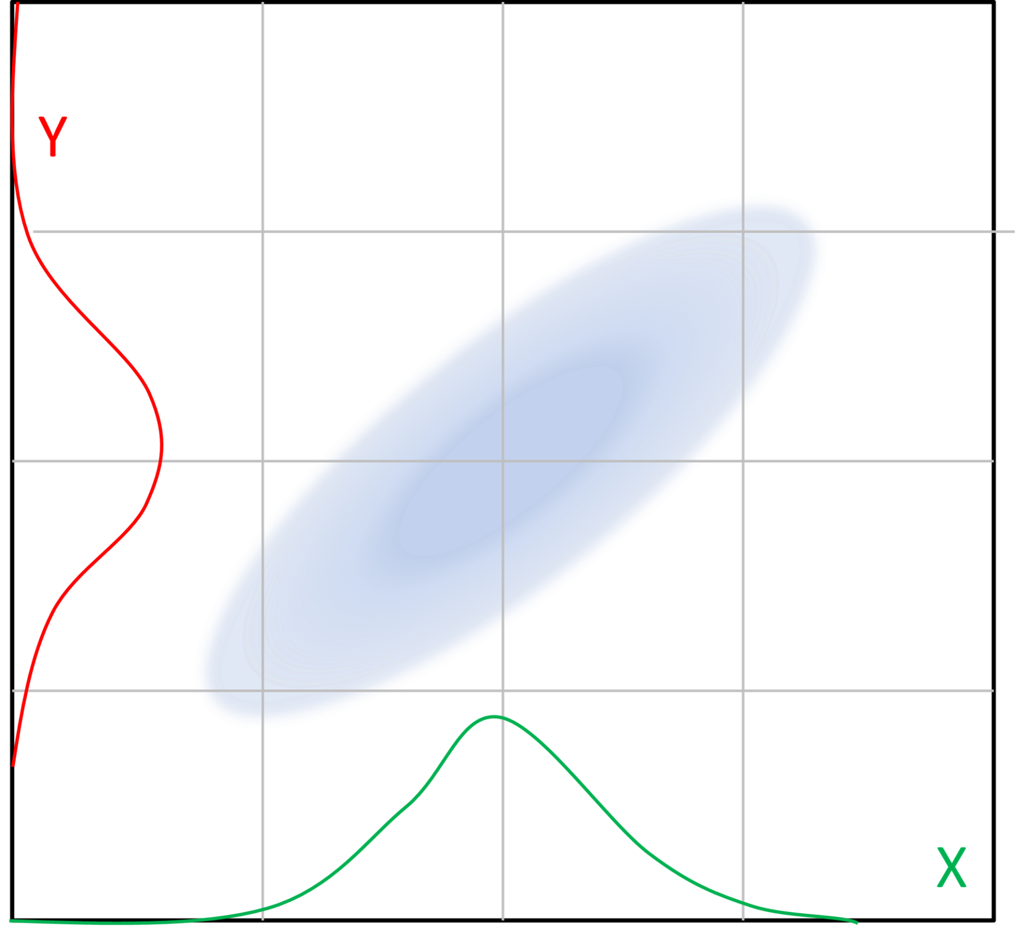
Ionization chambers are well-established for particle beam therapy diagnostics. It is typical to measure the position and shape of the beam using parallel readout from strip electrodes in orthogonal planes transverse to the beam direction. However this method has a shortcoming for beams that are not aligned with the sensing axes, such as inclined elliptical beams.
An inclined elliptical beam cannot be distinguished when viewed only as a projection onto X and Y axes. However such a beam may invalidate treatment planning assumptions, and therefore must be detected by any effective beam diagnostic system.
To detect this condition, we have developed a beam imager, a transmission ionization chamber with pixel readout, which provides a true 2-D representation of the beam spot. Two of these chambers placed just either side of isocenter allow beam trajectory and divergence to be determined by simple trigonometry.
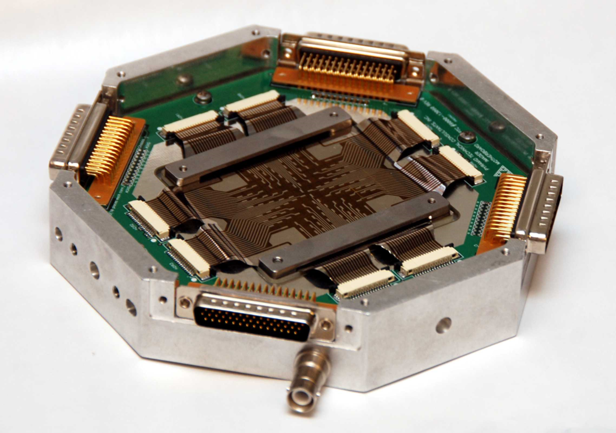
Compact ion chamber with 128-pixel readout electrode, shown with windows removed. The readout pixel pitch in this version is 3.8 mm square. The pixilated electrode has been fabricated in 12.5μm polyimide film.
Ionization chambers have a gain factor that is a function of the beam particle type, energy and the filling gas. It is desirable to verify the IC calibration using a direct measurement of delivered charge. A beam collector is included after the second ion chamber. This gives a direct confirmation of charge per dose spot in Gigaprotons, that is almost independent of energy. A traditional Faraday collector for high energy particles requires a vacuum volume with thin entrance window, deep cup collector and magnetic and/or electrostatic suppression. However the resulting assembly is bulky and relatively fragile. It is not suitable for a isocenter diagnostic system intended for regular and convenient use. The monolithic beam collector [1,2] however is well-suited. With careful design it can provide accurate measurements.

Assembly of two ion chambers and beam collector. Nominal position for the isocenter plane is equidistant between the chambers. The mechanical assembly is mounted on a motion system that can position it anywhere in the beam scan field on the isocenter plane. A optional gimbal arrangement allows it to be rotated to track gantry rotation.
The 2-D ionization chambers are each read out by a Pyramid I128 multichannel electrometer [3], and the beam collector is read out by a IC101 electrometer [4]. Specially written software collects the data from the electronics, fits ellipses to the beam profiles using the method of moments and displays the computed data for the user, including the semi-major axes and ellipse rotation. A smoothing algorithm interpolates between the individual pixels to improve the visualization of the beam spot on the screen. The trajectory and divergence of the beam are calculated using the known spacing of the two ion chambers. The beam charge is integrated on the beam collector, and can be reset for each spot in the treatment map.
Results
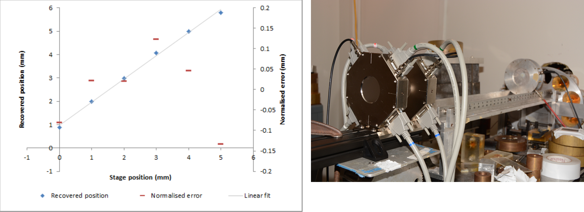
The chambers worked without problem; the beam position and shape were recovered with excellent stability. Using a motion stage to move the assembly in one mm steps relative to the beam showed clear resolution of the moves; the limiting position resolution after fitting is less than 10% of the pixel pitch.
The pair of pixilated ion chambers under test on beamline 3A at MGH. A beam of 239 MeV protons was used. 256 parallel channels of charge measurement were collected and digitized by by I128 electronics located in the experimental room and transmitted to the control computer over Ethernet.
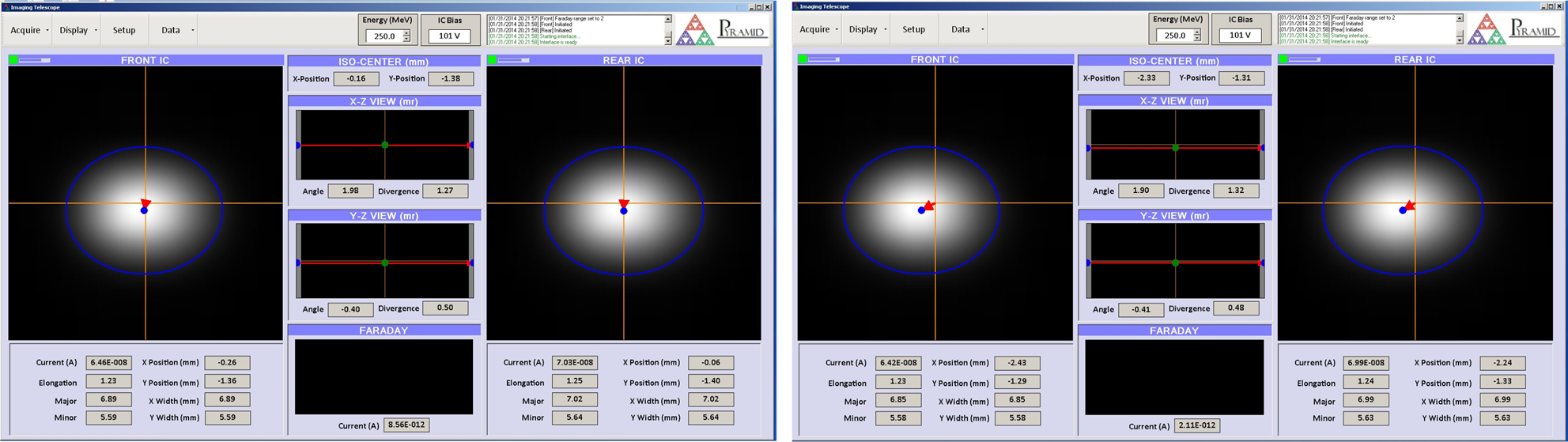
A deliberate small beam shift of about 2mm in each axis was detected easily:
Successive screen shots showing detection of a beam shift of about half of the pixel size. The software allows the data to be logged to a local files or exported to EPICS [5]. A replay facility allows the user to step through a sequence of recorded measurements to look for transient effects.
An initial beam collector design (BC-100, now replaced by the BC-75) was made using a copper collector block able to stop 250 MeV protons, coated with polymer and conductive epoxy overlayers. Numerical simulations using MNCP and TOPAS are in progress to find the construction that gives maximum accuracy. A set of measurements taken at MGH compared readings on the BC-100 with readings taken on the reference NFC from the Harvard Cyclotron Laboratory [6] and with an MGH beam collector. A carefully calibrated small-gap ion chamber gated the accelerator so that a fixed number of ion chamber monitor units were delivered for each measurement.
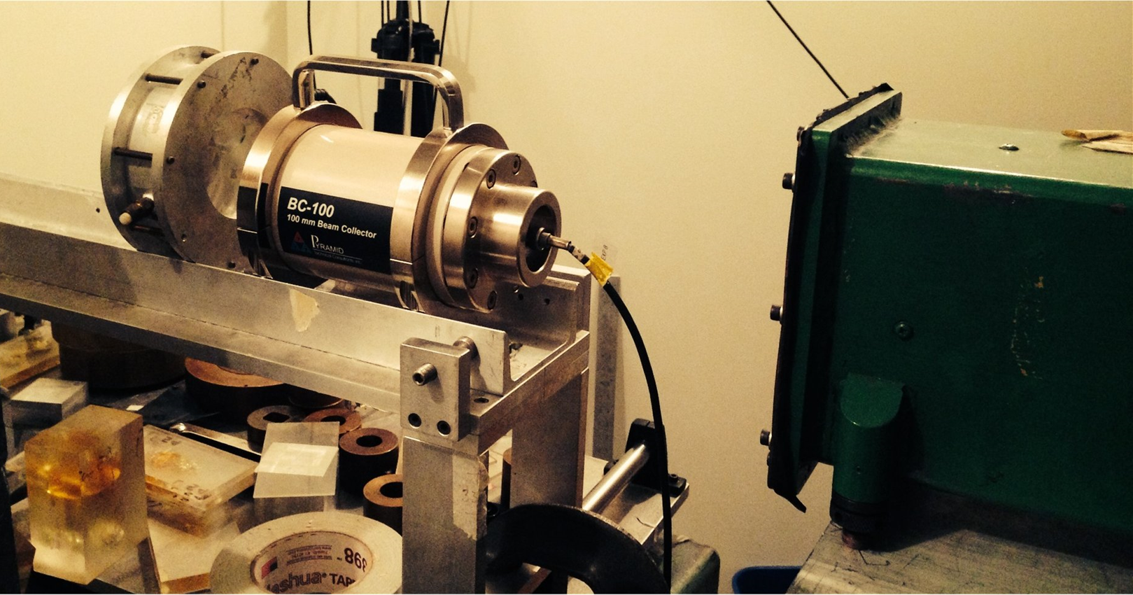
BC-100 beam collector under test at MGH. The dose control ion chamber and part of the reference NFC are visible. Sequential measurements were taken with the NFC, the BC-100 and an MGH beam collector.
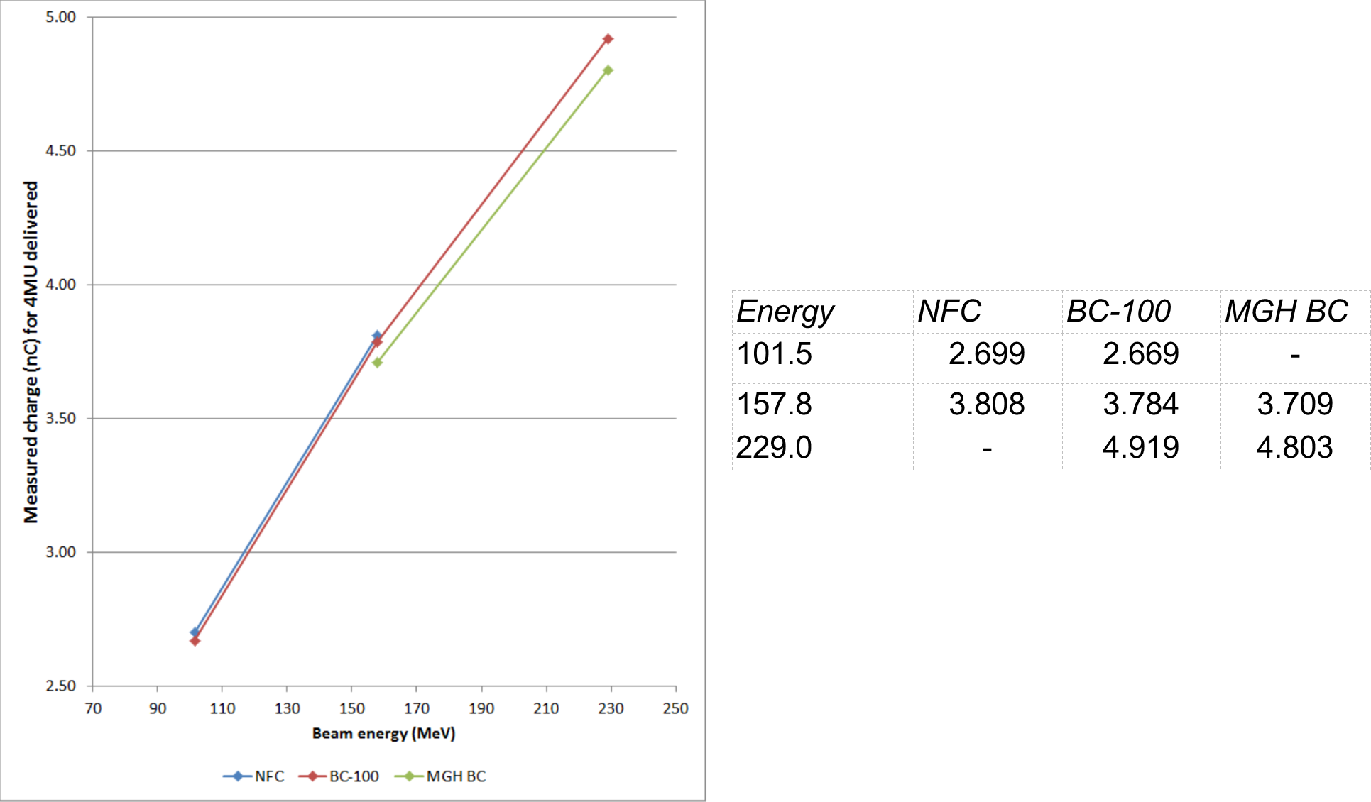
It is typical that beam collectors using the same principle as the BC-100 show a small deficit in measured charge relative to the reference NFC. The measured deficit for the BC-100 was very small, however, only -0.62% at the highest energy accessible to the NFC. This is very promising for its use as a reliable absolute dose measurement device.
The table shows the measured charge in nC for 4 MU delivered at three beam energies.
Conclusions and next work
We have shown that a combined isocenter diagnostic system can provide information needed to characterize a spot beam. In the next step we shall use the prototype system for initial tests in a PBS treatment room [7].
A multilayer Faraday collector is under development which will provide beam energy .measurement as well as dose. A precision X-Y-theta motion stage will allow the sensors to be moved to any point in the scan field and rotated.
Acknowledgements
We are grateful to Ethan Cascio for his efficient assistance taking data at MGH, and to Dr Jay Flanz for permission to take data on the MGH system.
References
[1] B. Gottschalk, http://users.physics.harvard.edu/~gottschalk/
[2] D.K. Bewley, Phys. Med. Biol. 16 (1971) 131
[3] Datasheet: I128_DS_121120
[4] Datasheet: IC101_DS_131223
[5] http://www.aps.anl.gov/epics/
[6] L. Verhey et al, Radiation Research. 79.1 (1979) 34
[7] J.Gordon et al., PTCOG 53 poster 61