A Multipole Magnet for Pencil Beam Scanning
Abstract
Space is at a premium in particle therapy gantry systems intended for pencil beam scanning. A scan magnet system located after the final bending magnets is a common solution, which simplifies the overall gantry optics. However space is particularly limited here if the overall gantry dimensions are to be kept under control. The aim of this work was to design, build and test a combined function beam scan magnet for particle therapy which provides good field size, good speed and low beam aberration in a compact format. We present details of a multipole magnet design that provides beam deflection over a circular field, with no preferred axes. The dipole field quality is good in the volume of the magnet bore, resulting in low aberration at all points in the field. It is possible to do dynamic beam spot shape modification on a spot by spot basis.
Scan Magnet Options
Fast magnets are needed to deflect the beam spot to the required point in a scan field for pencil beam scanning. Gantry optics are simplified if the scan magnet system is placed after the final bending magnet in a gantry. A well-known solution is to use two independent dipole magnets to deflect the beam in the two transverse directions (1). However the magnets must be arranged one after the other along the beam path, and space here is limited if the gantry size is to be kept within bounds. The second magnet needs to accommodate the fan of trajectories produced by the first. This dictates a relatively large gap, and ultimately a higher inductance, slower magnet.
Combined function magnets require less distance along the beam path, and can be designed to give similar dynamic performance in both axes (2). However the superimposition of two crossed dipoles leads to higher order field terms which produce unwanted beam spot distortion away from the centre of the scan field.
A combined function magnet that provides low aberration over the field would combine the benefits of these two approaches.
Multipole scanner principle
Normally a multipole magnet such as a quadrupole or sextupole is connected with all coils in series carrying identical current. The interconnections ensure alternation of the current directions in the coils to produce a field with no dipole component, and a dominant multipole field, for beam shaping purposes. However we can connect the opposing coil pairs in a multipole magnet separately to bipolar power supplies and thereby create a magnet with a dynamically configurable field in its bore (3). In the general geometry, there are (thus opposed pole pairs) with coil currents at angles to a reference direction.

Generalised multipole geometry To get a deflection direction angle , we set the coil currents to
The deflection direction can be chosen freely – it’s not constrained by the pole angles, and the scan field is circular. This means that there is no preferred direction, and the full deflection is available along any direction at the patient position. This could be helpful to reduce the number of patient positioner moves. The amount of deflection is set by an amplitude factor that scales all the coil currents.
Octopole Design
The octopole was chosen as a good compromise between dipole field quality and complexity. A design study using Opera 3D (4) investigated various values of magnet length and bore diameter to achieve good performance for 230 MeV protons. A 500 mm long laminated steel magnet with 120 mm bore was chosen, with peak DC coil currents of 400 amps giving deflection up to 6 degrees in any deflection direction. The calculated slewing rate is greater than 1400 degrees per second with a 375 V power supply.
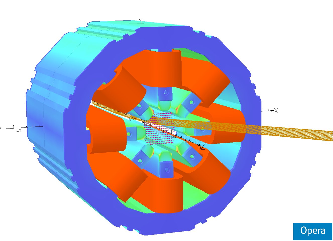
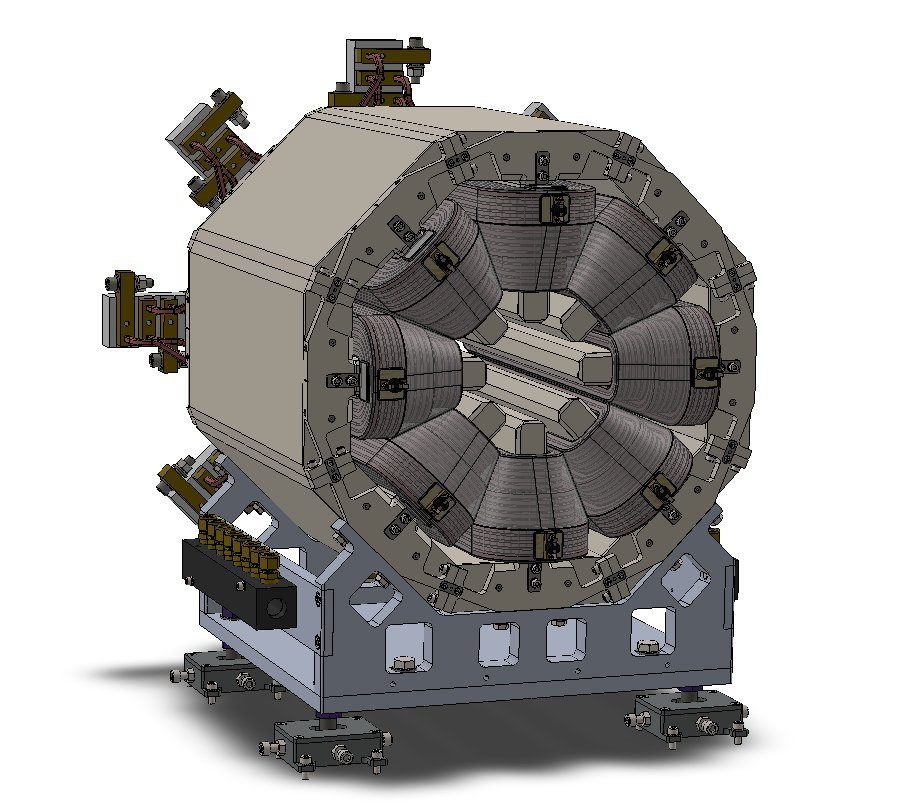
Electromagnetic and mechanical models of the magnet
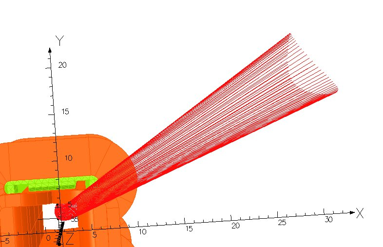
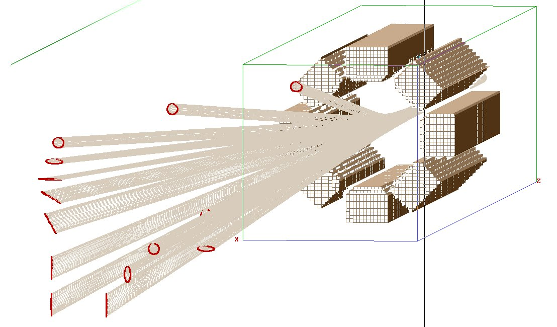
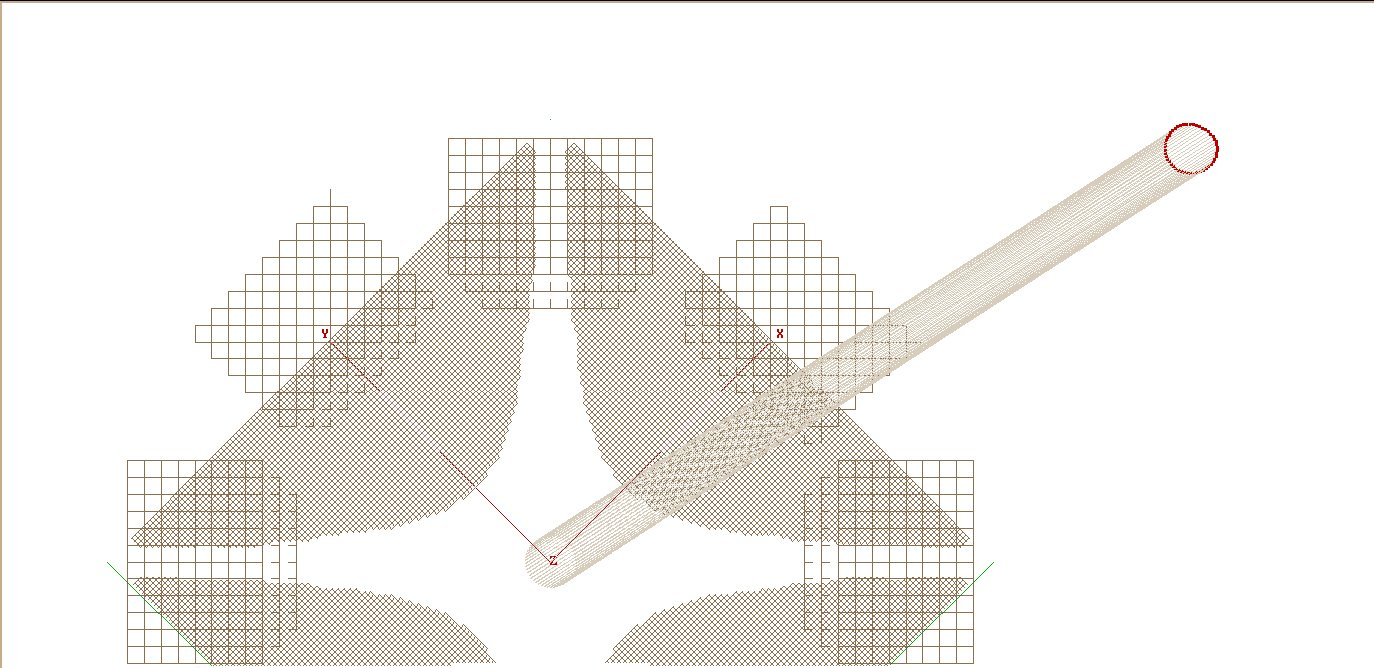
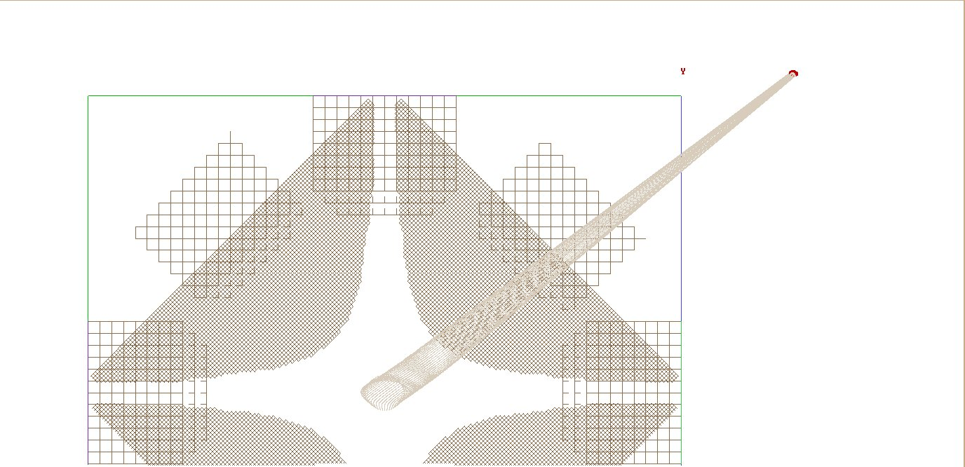
A simple pole figure that approximates the optimal hyperbolic profile was designed for ease of manufacture. Ray tracing simulations show low distortion of a circular injected beam, even at full deflection.
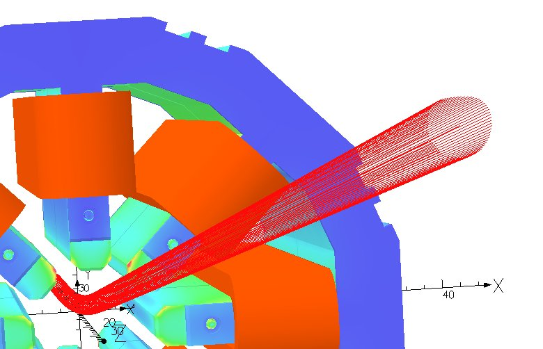
Distortion of a 1 cm radius circular parallel injected beam at 6.1 degrees deflection in an octopole scan magnet compared to 4.6 degree deflection in a crossed field scan magnet
The octopole magnet is now in manufacture for evaluation and use at MGH. A program of tests will confirm the field quality at all rotation angles, and dynamic performance. An important part of the development will be conversion of treatment plans to pencil beam scanning maps to take advantage of the features of the multipole scan magnet.
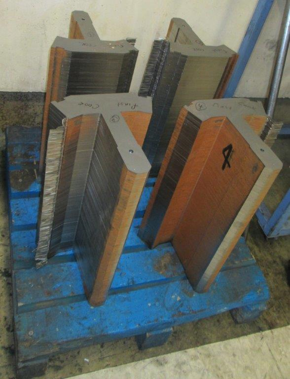
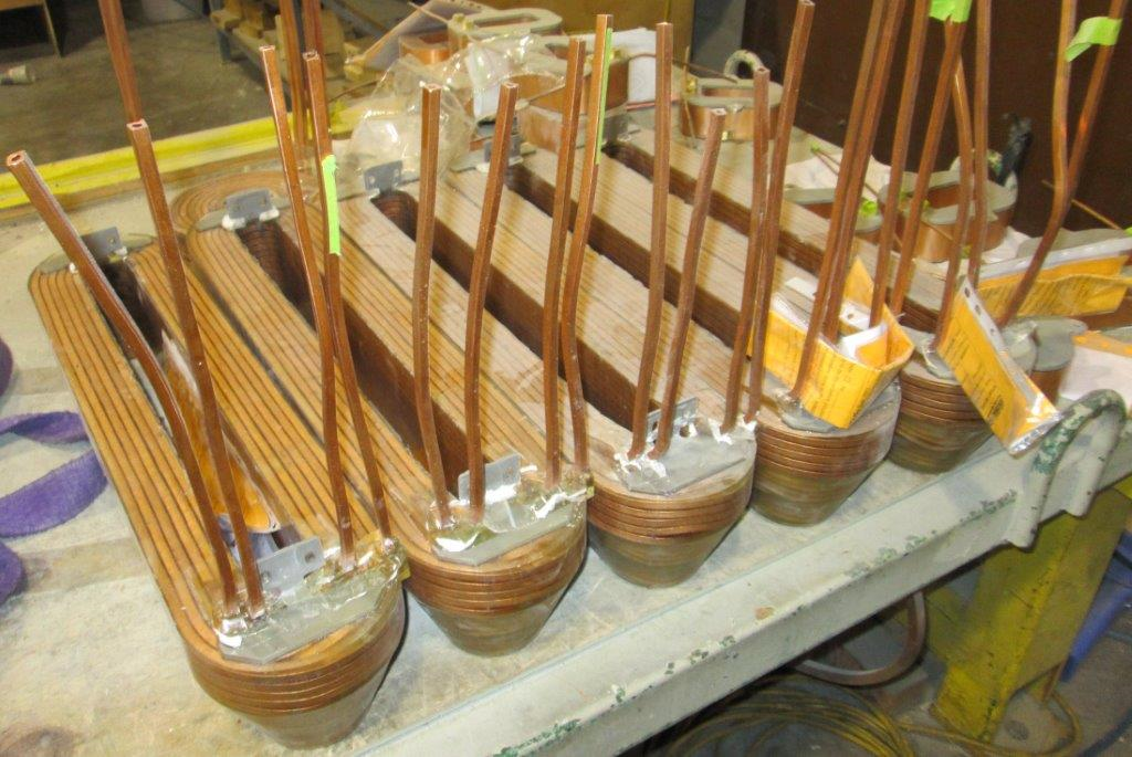
Lamination stacks and coils in manufacture for the prototype octopole magnet
Amplifier system
The octopole scan magnet requires a more complex power supply than conventional separated dipoles or combined function magnets. The availability of a cost-effective multichannel amplifier system is an essential part of the design. A water-cooled +/-400 amp amplifier module operating off a 400 V bus has been designed to meet this need. Four such modules on a common DC bus power the magnet. An embedded controller converts requested spot positions to coil current settings for the four coil pairs.
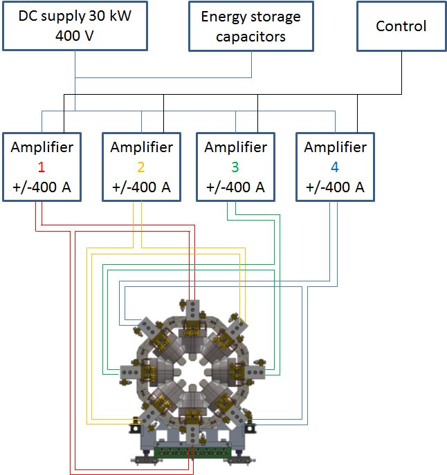
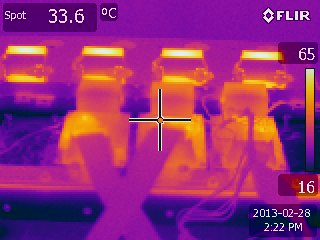
Multichannel amplifier block schematic and thermal image of the power bridge prototype running at 400 A DC
Dynamic beam shaping
Deliberately departing from the sinusoidal distribution of coil currents that produce a clean dipole field allows the shape of the beam spot to be modified at the same rate that it is moved. This presents intriguing possibilities for improved conformal dose delivery. In particular, if each individual coil is provided with its own power supply, then a clean quadrupole component can be added to the field. The quadrupole component can be rotated arbitrarily with respect to the dipole component. As an extreme demonstration, a low emittance beam can be converted from a circle to a line, and the line can be rotated and translated.
Calculated translations and shape manipulation of an originally circular beam spot, calculated using Simion 3D (5)
The quadrupole component of the scanner can be made part of a quadrupole doublet if a discrete fast conventional quadrupole magnet is added upstream of the scan magnet. Focusing and defocusing of the beam spot in two axes is then possible.
Ray trace simulations looking back along the beam axis: deflection only, and deflection plus quadrupole doublet focusing
References
[1] (Reference needed for the IBA scanning nozzle)
[2] V. Anferov, Med. Phys. 32, 815 (2005)
[3] US patent 8,378,312 B1
[4] Opera 3D version 15R1, Vector Fields Software, Cobham Technical Services.
[5] Simion 3D version 8.0.3, Scientific Instrument Services, Inc.