A Simulator System for the Verification of Pencil Beam Scanning Dose Delivery Control Systems
Background and Aims
Verification and validation of software and electronic hardware for a new or updated pencil beam dose delivery system (PBDDS) is a major undertaking. Many exception cases must be tested. Access to the physical hardware is at a premium and liable to unscheduled interruptions. Key components such as the accelerator, magnets and ion chambers may not respond in a predictable way. It is slow and may be harmful to deliberately invoke certain fail conditions.
We have addressed this problem by developing simulators that closely reproduce the known nominal behavior of these prime components, providing multiple analog and digital signals that connect directly to the actual PBDDS. The PBDDS receives and executes a treatment map as usual. An accelerator simulator unit receives commands from the PBDDS as would the real accelerator and responds accordingly. Ionization chamber simulators coordinate with the accelerator simulator to create multiple current readings with appropriate spatial and temporal profiles.
Controlled errors of almost any characteristic can be introduced at specific places in the irradiation. It is then simple to correlate the response of the PBDDS to these introduced errors. This is not intended to replace completely exception testing on the real system, but it permits a much increased range of cases to be run and evaluated in a reasonable time using an automated procedure.
We describe in detail the hardware that has been developed for simulation and how it is integrated into a complete simulation system for dose delivery.
Architecture
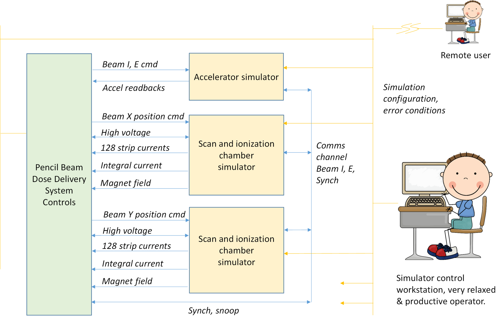
The simulator system comprises a standard set of control electronics and associated software for a PBDDS. In some cases some beam transfer line controls may also be included. Then to match these devices are hardware simulation electronics that mimic the response of sensors such a ionization chambers, Hall probes, power supply monitors and so on. The primary simulation devices are:
- An ionization and PBS scan system simulator (“ICSIM”) which receives demands for beam energy, current and position and generates ionization chamber, magnet power supply and magnet field signals. As many of these units as necessary are used to make up the full complement of redundant integral planes, and X, Y axes.
- An accelerator simulator (“ACCELSIM”) which emulates the interface to the specific accelerator and passes the demands for beam energy and current through to the ICSIM units.
The simulation electronics are networked to a supervisor computer so that their behavior can be controlled to produce various calibrations and specific out of tolerance and fail conditions. Both simulator and the standard PBDDS control computers can be accessed via VPN for remote access by other developers and testers.
ICSIM Device
The ICSIM is a flexible set of analog and digital interfaces controlled by an embedded processor. It provides 128 current outputs to represent ionization chamber strip electrode signals, two currents that represent integral plane signals, a voltage representing a Hall probe readout, a high voltage output representing the loopback sense from an ionization chamber, plus other voltages for signals such as temperature, pressure and humidity readbacks.
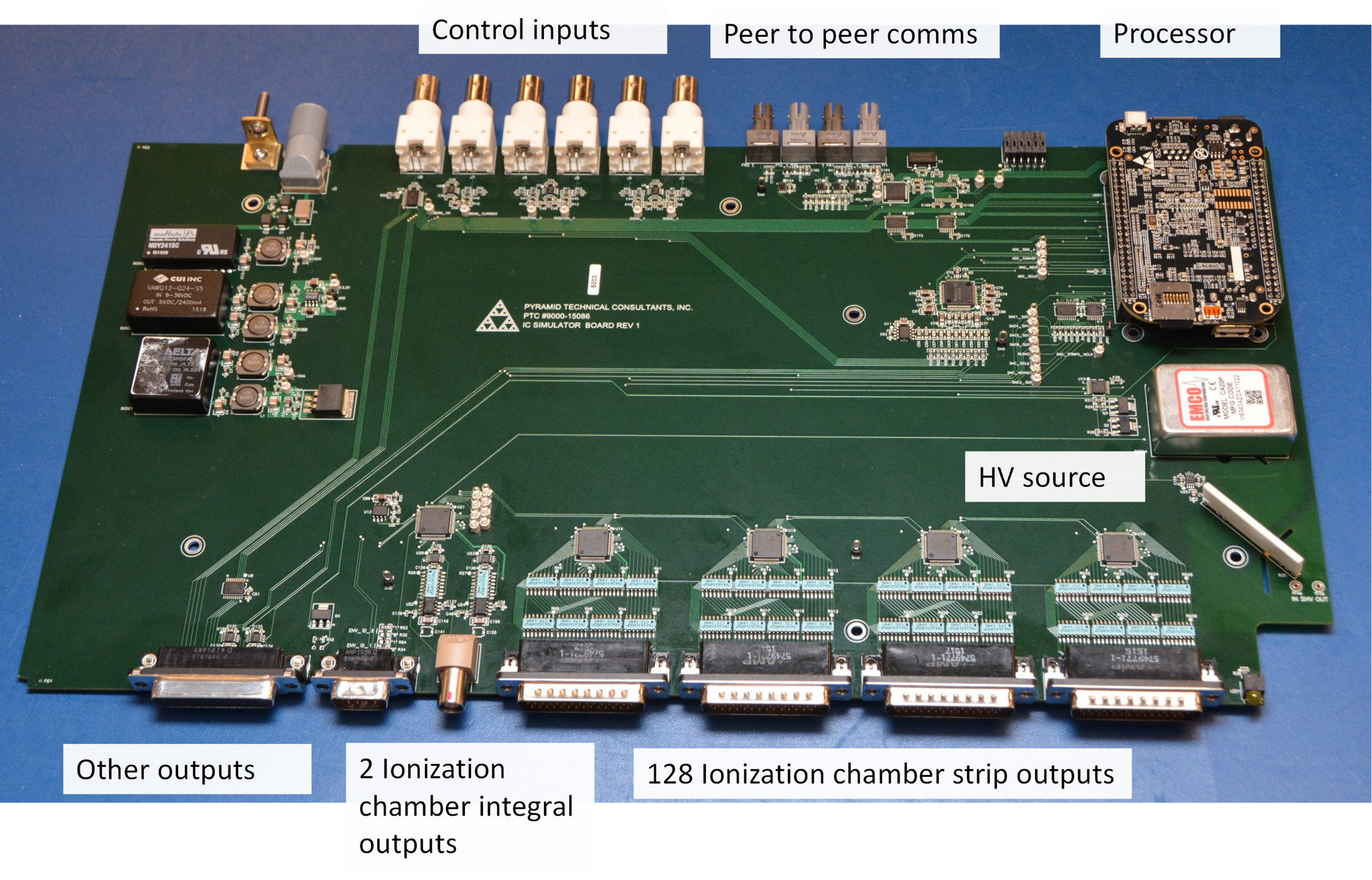
The ICSIM outputs are updated based on the inputs every 110 µsec. For example, if a map calls for a particular spot charge, energy and position the ICSIM will receive the resulting control signals for scan magnet setting from the PBDDS and beam energy and current settings from the ACCELSIM. The ICSIM will compute the magnet settings using the configured magnet calibration functions including effects such as saturation and hysteresis, and do a voltage-limited slew to the new settings, while providing outputs to simulate magnet power supply Hall probe readbacks. It will compute beam positions on ionization chambers and send out patterns of currents that represent the signals from ionization chamber strip electrodes and integral plane electrodes. The total charge in the signals are a function of the beam current, beam energy, chamber high voltage, temperature and pressure. The currents that would be integrated on chamber strips are pre-computed in normalized form and placed in a lookup table, then simply scaled in width and amplitude in real time.
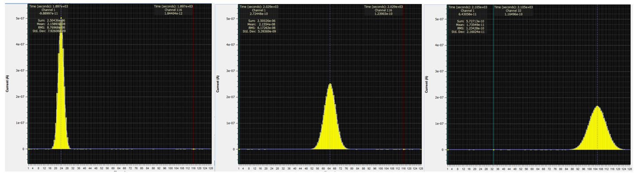
ICSIM output as recorded by PBDDS electrometers - beam moving across an axis under control of a scan magnet demand signal from the PBDDS and changing width as configured in the simulator.
Noise and anomalous conditions can be introduced at will, or as part of an automated test sequence. Many typical anomalous beam shapes can be produced by simple addition of two Gaussians.
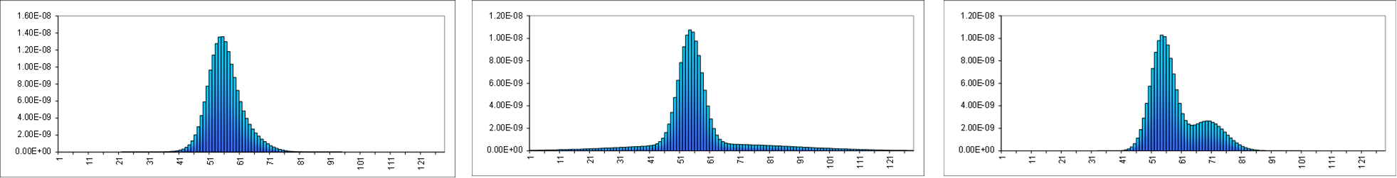
Asymmetric peaks, haloes and double peaks created by adding two Gaussian functions.
Incorrect high voltage on ionization chamber electrodes is an insidious failure mode in real systems. The ICSIM allows an arbitrary high voltage to be returned to the PBDDS on the loopback connection. This allows high voltage absence, sagging and instability to be simulated.
Running Maps
The completed simulator provides all the control connections required by the PBDDS, so any maps that can be run on a real system can be run on the simulator. The simulator devices as well as the PBDDS devices get copies of the map so that errors can be introduced as deviations beyond map limits expressed in clinical or device units, and present for specified durations.
Testing can comprise running an automated sequence of maps with the simulator programmed to introduce particular errors at known points so that correct response of the PBDDS can be checked. Errors can also be introduced asynchronously by adjusting the simulation configuration, or by manual switching of digital and analog signals, while a map is running. Signal breakout connectors are provided so that time-critical events can be logged with test equipment such as digital oscilloscopes.
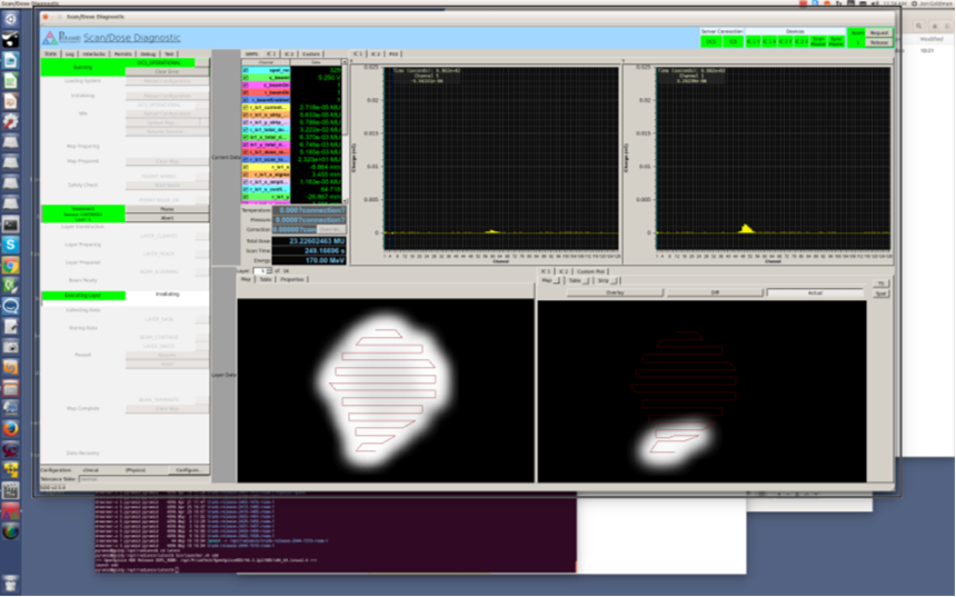
A map during execution with full simulation of the accelerator and nozzle hardware.
Further Developments
- The units built to date provide simulation of cyclotron and synchrotron accelerators. This is now being extended to include fixed cycle pulsed beam machines such as synchrocyclotrons and linacs.
- The simulation cycle time will be reduced to further improve the ratio between the PBDDS cycle (typically 0.2 to 5 msec) and the simulation cycle time.
- Accelerator control in the existing simulators is by analog voltages, currents and digital levels. Some particle therapy systems use message-based control over secure communication channels, so an upgraded version of the ACCELSIM device is in preparation to allow this.
- Support will be added for arbitrary beam shapes such as collimated beams.
- Support will be added for time-dependent behavior such as the beam turn-off decay profile.
- It is very useful to be able to reproduce behavior observed on a real machine at a customer site. A future enhancement will allow specific recorded patterns of system response to be programmed into the simulation control to allow the interaction between a particular machine configuration and irradiation map to be re-created at will in a controlled environment.