Scanning Amplifier Implementation at Massachusetts General Hospital
Abstract
Particle beam scanning provides the opportunity for the most conformal dose distributions in radiotherapy. Scanning is accomplished, in the transverse direction with magnetic dipoles to deflect the particle beam. These dipoles are powered by fast amplifier electronics. Some of the challenges include making quick and precise movements of the beam with a minimum of settling time and a maximum velocity in order to reduce the overall treatment time and to allow for the possibility of target motion compensation. It is also the case that different styles of scanning magnets can have different parameters which are subject to the same stringent requirements. MGH, working with PTC and IECO have chosen a fast amplifier originating from magnetic resonance imaging technology modified for the specific requirements of beam scanning. The challenges of this implementation will be described. Results of an implementation including beam performance and timing will be discussed.
Introduction
Particle therapy centers look increasingly to magnetic beam scanning to supplement or replace scattering techniques, to obtain the best conformal dose distributions. An important part of the beam scanning system is the high current amplifiers which drive the magnet coils. The requirements for the amplifiers can vary considerably depending on the design of the scanning magnets and on the type of scan (pencil beam spot scanning, or uniform raster scanning).
The fixed beamline room 3A at the MGH Francis H Burr Proton Therapy Center is being refitted as a dual mode scattering and scanning treatment and research room. This required the development of a flexible amplifier system to meet the needs for room 3A and to also act as backup for the two gantry treatment rooms.
Scanning amplifiers
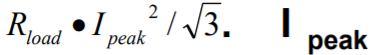
The beams used in particle therapy have relatively high rigidity (typical range of 1.0 to 2.5 Tesla-meters for protons). The need for larger field sizes (e.g. 40 by 30cm), shorter Source to Surface Distance (SSD) (e.g. 1.5m) dictates power supplies which can deliver high maximum currents (+/-300A to +/-1000A). The requirement to minimize treatment time results in a specification for high compliance voltage to drive the magnet inductance (e.g. hundreds of volts). Amplifiers able to deliver these current and voltage ratings over four quadrants of operation (positive and negative voltage and current) have already been developed for MRI gradient coils. These use switching bridge topology with interleaving of parallel bridges to give a high effective switching frequency, and thus low noise and ripple after filtering. The current and voltage ratings needed to drive gradient coils are also suited to beam scanning. However, the MRI application requires the amplifier to deliver only a short high current plateau (max - few tens of msec) with relatively low duty cycle, and thus moderate average power. In the particle therapy application a treatment may last minutes during which time the amplifier can operate at high continuous power. Uniform scanning (a specific form of beam wobbling) is less demanding on the amplifier. It is generally performed using regular triangle waveforms in the few Hz to hundreds of Hz range; given adequate energy storage in the amplifier, the average power delivered to the load can be taken as I peak can be higher than the continuous hold capability of the amplifier or magnet coil. In pencil beam spot scanning, by contrast, if we don’t want to constrain the irradiation map in any way, we must work within the continuous (or at least tens of seconds) rating of amplifier and coils. This allows a cluster of beam spots to be delivered at an extreme limit of the available field, for example, without needing to worry about a shutdown due to overload or overtemperature. The average power will be close to while the beam is positioned near the deflection limit. Thus a uniform scan field size, albeit prior to collimation, will generally be greater than a pencil beam spot scanning field size for a given amplifier/magnet combination. In either case the DC power supply that feeds the amplifiers must be sized based on the highest expected continuous RMS power
MGH requirement
Fixed beamline room 3A at the MGH Francis H Burr Proton Therapy Center is being refitted as a dual mode scattering and scanning treatment and research room (1). A two-axis fast scanning magnet developed and built at the Indiana University Cyclotron Facility (IUCF) (2) has been installed on the scanning line. This magnet was designed for uniform scanning, and has low inductance in both axes.

IUCF magnet (right) on the room 3A moveable beamline table
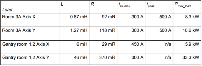
An additional requirement was that the amplifier should be able to act as a backup for the gantry treatment rooms 1 and 2, with automatic switching highly desirable. The summary of the loads was:
The amplifier needed to integrate simply with a Pyramid scan/dose control system. Risk assessments had determined that independent redundant readback of the current outputs was required, so the design needed to accommodate this.
Amplifier solution
IECO provides a two-axis configuration of the established PA-400-350 air-cooled amplifier modules (3), configured as master-slave-slave on axis X, and master-slave on axis Y. Air-cooled units are generally less compact than equivalent water-cooled ones, but there was sufficient space available. The installation is more straightforward, and servicing is more convenient. The five amplifier modules each contain six identical power bridge cards which can be quickly replaced if necessary without special setup.
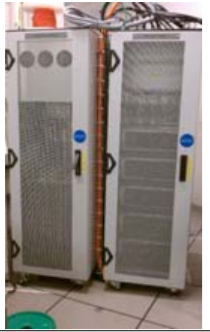
IECO amplifier system installed in the power supply room
A 70 kW power supply was developed to meet the worst case continuous operation on both axes in the gantry rooms plus some margin for future extensions. A “coil identifier” feature is used to switch the amplifier tuning parameters under automatic control depending on which treatment room is in use.
Mounting and power was provided for Pyramid M10 and X32 units which program and control the two axes, and also read out redundant LEM IT700 current sensors. These were installed in the amplifier cabinet, but are completely independent of the amplifier control loops.
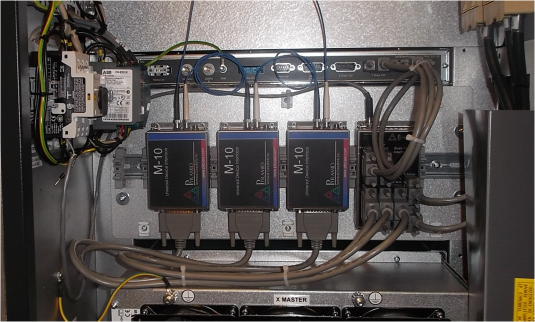
Pyramid controls installed in the amplifier cabinet
Test data
The amplifiers were connected to the IUCF magnet in room 3A. The slewing rates of the M10 units are configurable and were adjusted so that the amplifier remained within its safe voltage compliance limit of 300V, giving values of 275,000 A s-1 for axis X and 225,000 A s-1 for axis Y. To demonstrate this level of performance, a +/-250 A triangle waveform was delivered at increasing frequencies.
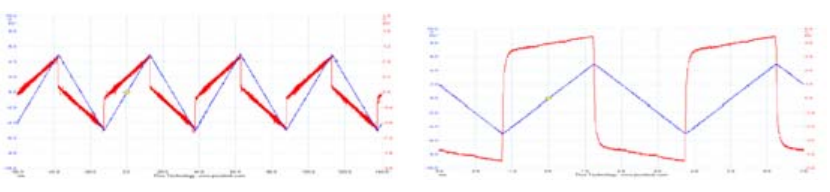
Amplifier current (blue) and Voltage (red) monitors for 20Hz (left) and 200 Hz (right) +/- 250 A triangle waveform
Extrapolating to a voltage limit of 300 V would imply a maximum triangle wave frequency of 280 Hz at this amplitude. This corresponds to 2460 degrees s-1 for protons at 230 MeV, or 100 m s-1 at the nominal isocenter plane of room 3A.
The form of pencil beam spot scanning in which the beam is gated off while moving between spots requires good slew rate, particularly for large moves. However for small position changes the analog bandwidth of the amplifier and correct tuning can be just as important for the total time required to move the beam spot. A Hall probe was positioned in the magnet bore, and the field steps were recorded and compared with the current step. 100 A steps were commanded while an IC128-25 ionization chamber (4) read out by I128 electronics was placed to measure the deflected beam. The amplifier monitor output shows the step completed in less than 600 usec. The corresponding field completed in 800 usec. The beam spot moved in less than 800 usec for the X axis and less then 950usec for the Y axis. There is no evidence of ringing.
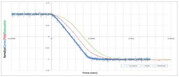
Normalized response to a slew-limited 100A current step (field = 0.55kG; position shift = 36mm)
A small 10 A current step completed in 250 µsec, and the corresponding field step in 350 µsec. What matters ultimately is the time taken for the beam spot to move.
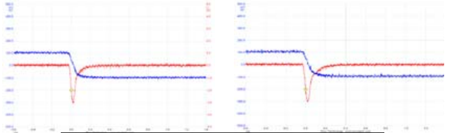
Small step (10A) current and voltage responses in each axis
An attempt to reveal any ripple or short-term instability on the amplifier outputs affecting the beam position or effective width revealed no effect and standard deviation was 0.03mm and 0.05mm respectively. However the beam spot was already fairly large in the test due to lack of the planned helium beam path, and it will be repeated when this is installed.
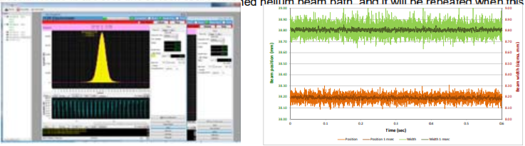
Position and width: Ionization Chamber histogram (left); Computed position and width (right) with 100 usec resolution
Further work
The next activities in MGH room 3A will focus on small spot delivery and full map execution. This will allow the amplifier performance to be measured under more revealing conditions. The ability to switch quickly between the room 3A and gantry room loads will be confirmed.
References
[1] J.Flanz, PTCOG 52 oral presentation.
[2] V. Anferov, Med. Phys. 32, 815 (2005)