Spot Position Measurement and Calibration for Pencil Beam Scanning Commissioning and QA Using a Large Area Sensor at Isocenter
Background and Aims
Accurate dose delivery for pencil beam scanning demands close control and monitoring of the lateral deflection of the particle beam. The precision of the method was appreciated from the start [1,2]; to translate precision to accuracy requires determining the functions C_x = f(x, y, Uk) C_y = f(y, x, Uk) where x and y are the required spot centroids on the isocenter plane, Uk is the beam kinetic energy and C_x, C_y are the control values for the electromagnets that deflect the beam.
An ideal magnetic deflection system would have linear relationships such as C_x = const.x.p where p = √(Uk2 + 2UoUk) is the momentum of the ions with rest mass Uo. In reality there are many factors which can complicate the relationship. The precise beam energy may be uncertain, the behavior of the scan magnets and their power supplies may be non-linear and there could be some coupling between the orthogonal axes. The lateral position calibration task is to capture all the systematic effects into the calibration functions. If the particle beam therapy system is a new design, there may be many effects to separate and understand, and for this it is important to measure over the whole scan field with good position resolution, good uniformity of response, and good time resolution.
We describe the design and use of a large sensitive area (45 cm by 45 cm) position-sensitive ionization chamber for scan calibration and measurement of dose conformity that can be accurately positioned at isocenter and used to sample the whole scan field at high spatial resolution.
In an ideal system the spot position and beam energy are the only input parameters for the magnet power supply control values C_x, C_y. In practice there are other influences that need to be understood
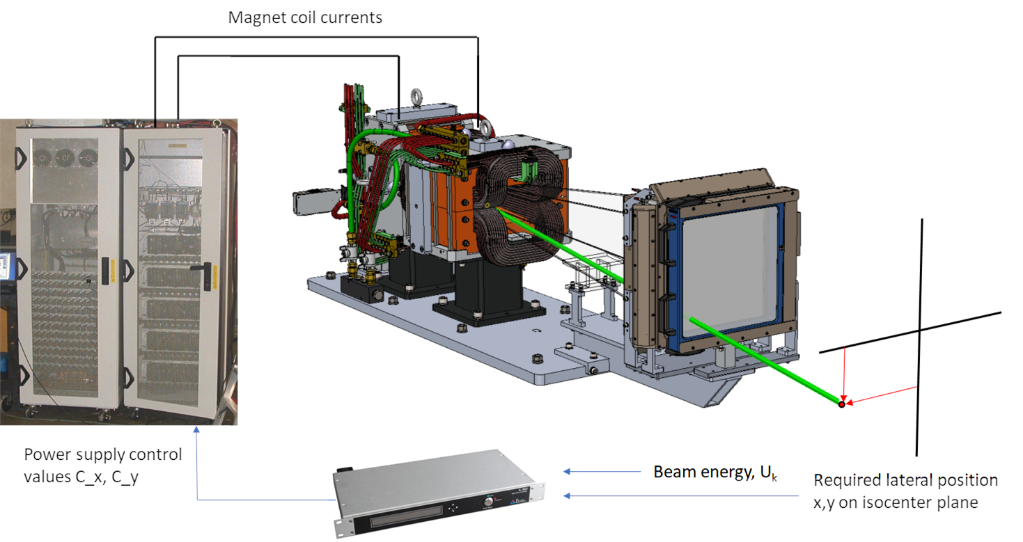
The calibration functions can be established either as lookup tables or as analytic functions that can exploit known physical relationships. In the first case the data set must be large enough to provide sufficient density of setpoints. Automation of data collection becomes almost mandatory due to the large number of readings required. The approach makes no assumptions about the processes that relate spot position to control values, thus it does not constrain the calibration in any way. The alternative, described later, is to exploit known physical relationships such as beam magnetic rigidity and magnet yoke saturation. This allows a smaller amount of data to describe the system response, and needs fewer parameters.
Large area isocenter detector
The use of position-sensing detectors including ionization chambers, diode arrays and CCD devices is well-established for machine calibration and quality assurance [3,4,5]. The objective of the current development was to offer a large continuous sensitive area in a robust and easy to handle device with good position resolution, good linearity and at reasonable cost. The resulting sensor is a transmission ionization chamber for use at the isocenter plane with 45 cm by 45 cm continuous sensitive area and 256 readout strips at a pitch of 1.75 mm in each axis. Typical centroid recovery precision from fitting the position peaks is better than 150 µm. The patterning of the electrode is done by lithographic PCB fabrication which provides accuracy relative to fiducials of better than 100 µm. The detector can be mounted simply on the patient table or installed on a gimbal to permit it to track gantry rotation. A typical maximum scan field size at isocenter for proton therapy is 30 cm by 40 cm which is easily contained in the sensitive area of the detector including allowance for misalignments, large spot dimensions and penumbra. The electrode assembly is mounted in a low mass frame with thin carbon fiber windows for beam transmission and external fiducials for alignment.

IC256-45 detector being aligned for scan pattern calibration measurements by Dr B Tesfamicael at the McLaren Karmanos Cancer Institute
Full electronic readout requires 512 processing channels. However the characteristic of “step and shoot” spot scanning, plus the time resolution of the readout, allows a 128 channel readout to provide the same position resolution by connecting strips on each axis in sets of four, offset from one another by 64 strips. Prior knowledge of the approximate spot position allows the data to be unfolded and the ambiguity to be resolved.
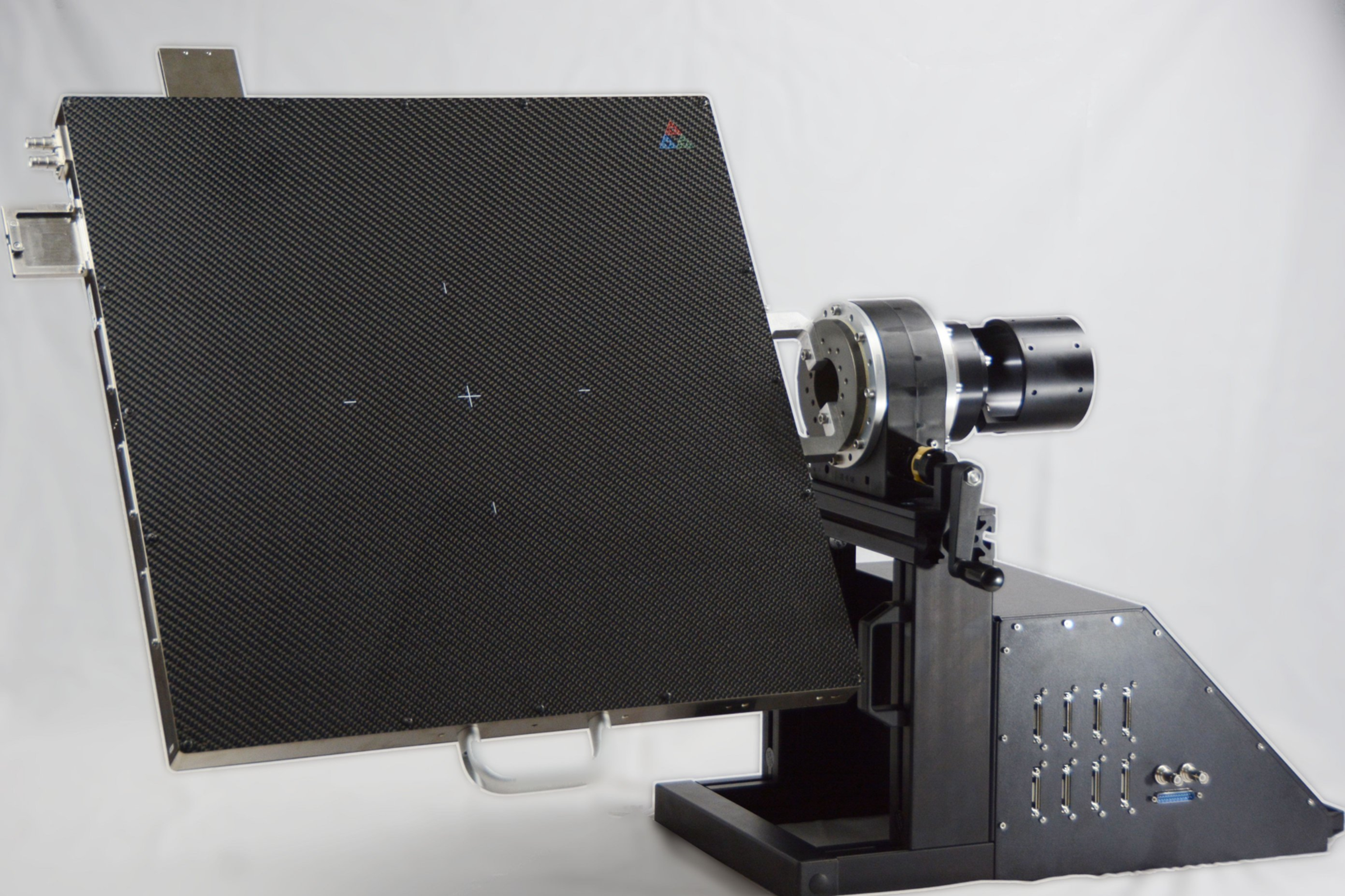
IC256-45 mounted on a motorized gimbal to allow the detector to be used at any gantry angle. The assembly is aligned in the treatment room coordinate system and the detector can also be located in the patient coordinate system using the room X-ray imagers.
Note that this system is able detect gantry pointing errors in the treatment room coordinate system, unlike the alternative of mounting the detector onto the end of the treatment
nozzle.
Alignment
Confirmation of spot positioning absolute accuracy should be in the coordinate system of the patient. The patient is typically aligned using X-ray imagers, therefore the imager defines the most important coordinate system. The IC256-45 can itself be imaged and therefore located in the patient coordinate system.
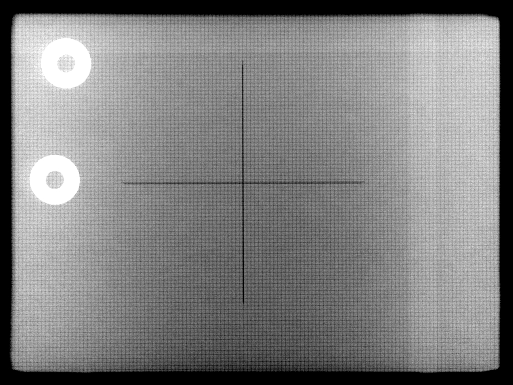
X-ray image of the IC256-45 ionization chamber retrieved from a DICOM image file showing the external fiducial (black cross) and the pattern of orthogonal readout strips which show as a cross-hatch pattern.
Calibration process
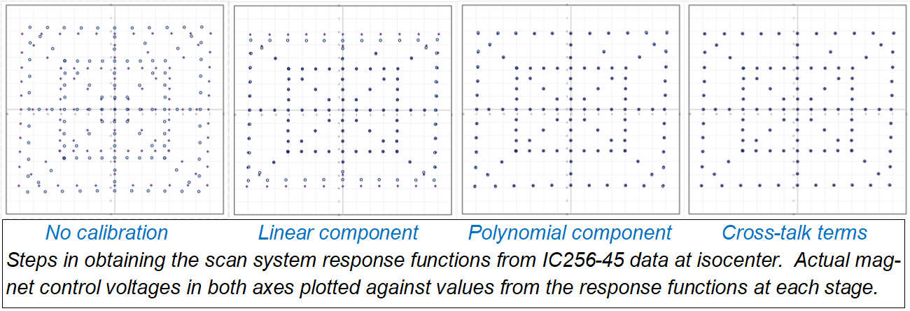
We have used the IC256-45 sensor to calibrate a scan system using continuous analytic functions. A single pattern of spots delivered at a reference maximum beam energy over the required full field provided the information needed to calibrate the deflection at all energies. The spot pattern provided independent information on linear response, non-linear response, and any cross-talk between axes.
Other potential energy-dependent effects such as variation of beam trajectory entering the scan system do not affect the calibration, because the resulting small offsets are within the acceptance of the scan magnets and can be simply subtracted. Beam offsets must be eliminated or compensated during beam delivery to a patient of course. Time-dependent behavior of the beam can be investigated because the data from the detector is time-resolved down to the msec level.
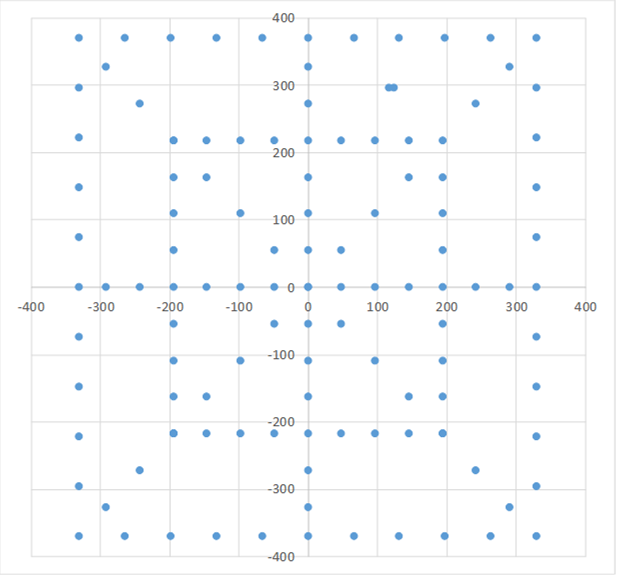
Calibration pattern in comprising 120 spots. It can be scaled as required in the two axes to suit the scan field. The pattern is run as an automated map at maximum energy to give a set of x(C_x, C_y) and y(C_y, C_x).
The isocenter spot positions measured by the IC256-45 were treated as the independent variable, and the calibration seeks the functions C_x = f(x, y, Ukmax) and C_y = f(y, x, Ukmax) that will be used to provide scan system control values. Firstly any residual misalignment of the IC256-45 is removed to centre the pattern on the axes. Then the linear component, due to the particle momentum, nozzle geometry and linear magnet system response is obtained by fitting the spots along the x and y axes with smaller deflections. Next the non-linear response at higher magnet excitation is fitted by a polynomial function that is tangent to the linear portion at a break point. Finally the spots with deflection in both axes are used to fit polynomial cross-talk functions. The process is iterated to give the best overall fit, then the accuracy is checked across the beam energy range.
Constructing a dose distribution map
An established use of array detectors like the IBA Dosimetry MatriXX PT [3,5] is to provide a 2D dose distribution for a reference spot pattern at some depth in water . By integrating during delivery of the complete pattern of spots, the MatriXX acts as “electronic film” with sensitive area 24.4 cm by 24.4 cm and pixels at 7.62 mm pitch. The raw data from the IC256-45 readout is time resolved, but can be simply integrated in time to provide an equivalent 2D charge density map measured with 1.75 mm readout pitch. If the computed gamma index pass criterion is not met, then the time-resolved record can often assist diagnosis.
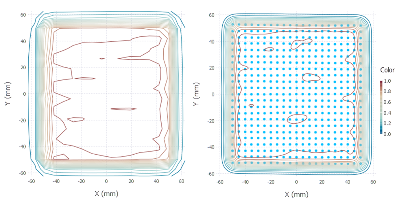
Dose distributions (250 MeV proton beam after 10 cm PMMA). MatriXX (left) and IC also showing measured spot centroids (right).
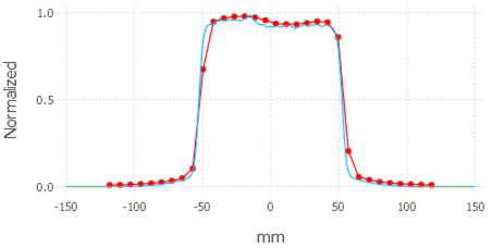
A profile extracted in the vertical axis shows how the continuous spatial resolution of the strip ionization chamber (blue) improves definition of the penumbra compared to MatriXX data (red).
Acknowledgements
We are grateful to to Dave Dickey, Dr Bijan Arjomandy, Dr B Tesfamicael, Kevin VanSickle, Dr Dmitri Nichiporov and Valeri Kozlyuk for assistance with data taken at the McLaren Proton Center.
References
[1] A.Lomax et al, Int. J. Med Phys. Research and Practice 31 (2004) 3150
[2] K.Matsuda, H.Itami, D.Chiba, K.Saito, Hitachi Review 58 (2009) 225
[3] B.Arjomandy, N.Sahoo, X.Ding, M.Gillin, Med. Phys 35 (2008) 3889
[4] J.Lambert, C.Baumer, B.Koska, X.Ding, J.Appl. Clinical Med Phys 15 (2014) 6
[5] IBA Dosimetry, Schwarzenbruck, Germany