Towards a Beam Quality Assurance Procedure for Particle Beam Scanning
Background
The dynamic nature of pencil beam scanning requires a complete rethinking of calibration and QA procedures. The system must be checked at the fundamental level, with beam energy, beam spot placement, beam quality and dose accuracy, measured accurately and efficiently. We are developing protocols and corresponding diagnostic equipment [1] to achieve this, in particular for “point and shoot” spot scanning. An integrated isocenter beam diagnostic system connected to the accelerator, beamline and imager controls can run an automated sequence that validates the full beam parameter space, or a subset for a particular treatment.
Using a simple delivery pattern of pencil beam spots, this study demonstrates how fundamental properties of pencil beam delivery parameters can be measured. The same isocenter diagnostic system can be used to find the imaging iso-center and check the coincidence with the radiation isocenter with the center pencil beam. Two-dimensional spot positions measured with the precision mechanical system can check the two-dimensional scanning magnet calibrations for a range of energies. Beam line optics and their pencil beam properties such as spot sigma and orientation can be checked as a function of gantry angle. The measurements of spot intensities using the monolithic beam collector can also be used to monitor the uniformity of the primary dosimetry ion chamber over the large area of the clinical range. A multilayer Faraday collector (MLFC) promises to provide an easy and efficient way of monitoring pencil beam energy.
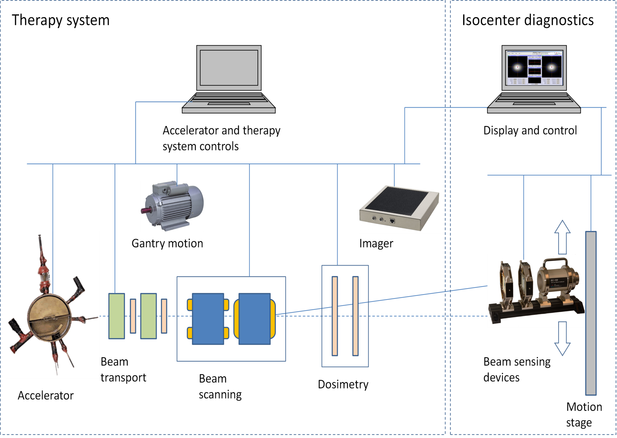
Isocenter diagnostics system connected to therapy system controls allows automatic execution of beam measurement sequences.
The diagnostic devices are typically a pair of pixilated ion chambers and a multilayer Faraday collector.
The immediate and obvious application of a diagnostic system that can measure all the critical pencil beam parameters quickly and automatically is to speed up system commissioning, especially for gantry beamlines where a large parameter space of beam energies and gantry angles must be characterized. The system can also be used for quality assurance of the basic parameters that affect the treatment, namely the intensity, shape, trajectory, position and energy of the beam [2-6].
Method
A pair of imaging ionization chambers a known distance apart is placed so that the isocenter plane lies between them. The beam is then stopped and measured in a beam stop. The prototype system, described in more detail here [1] uses a monolithic beam collector (BC-75) which measures the total beam current. The production version will use a multilayer Faraday collector (MLFC) [7] that also allows the energy and energy spread of the beam to be measured.
The whole mechanical assembly is mounted on a motion stage that can position it anywhere in the scan field. Alignment of the diagnostic system should be relative to the X-ray imager that in turn defines the patient coordinate system. For gantry beam lines, the whole diagnostics assembly is mounted on a precision gimbal so it can rotate to the nominal gantry angle. This is distinct from mounting to the gantry itself, and therefore allows errors in gantry rotation to be observed.
The motion stage cannot move as quickly as the beam, so only one beam spot location can be analyzed at any time. An alternative configuration avoids this restriction by reproducing the imaging IC components at multiple locations over the field.
Results
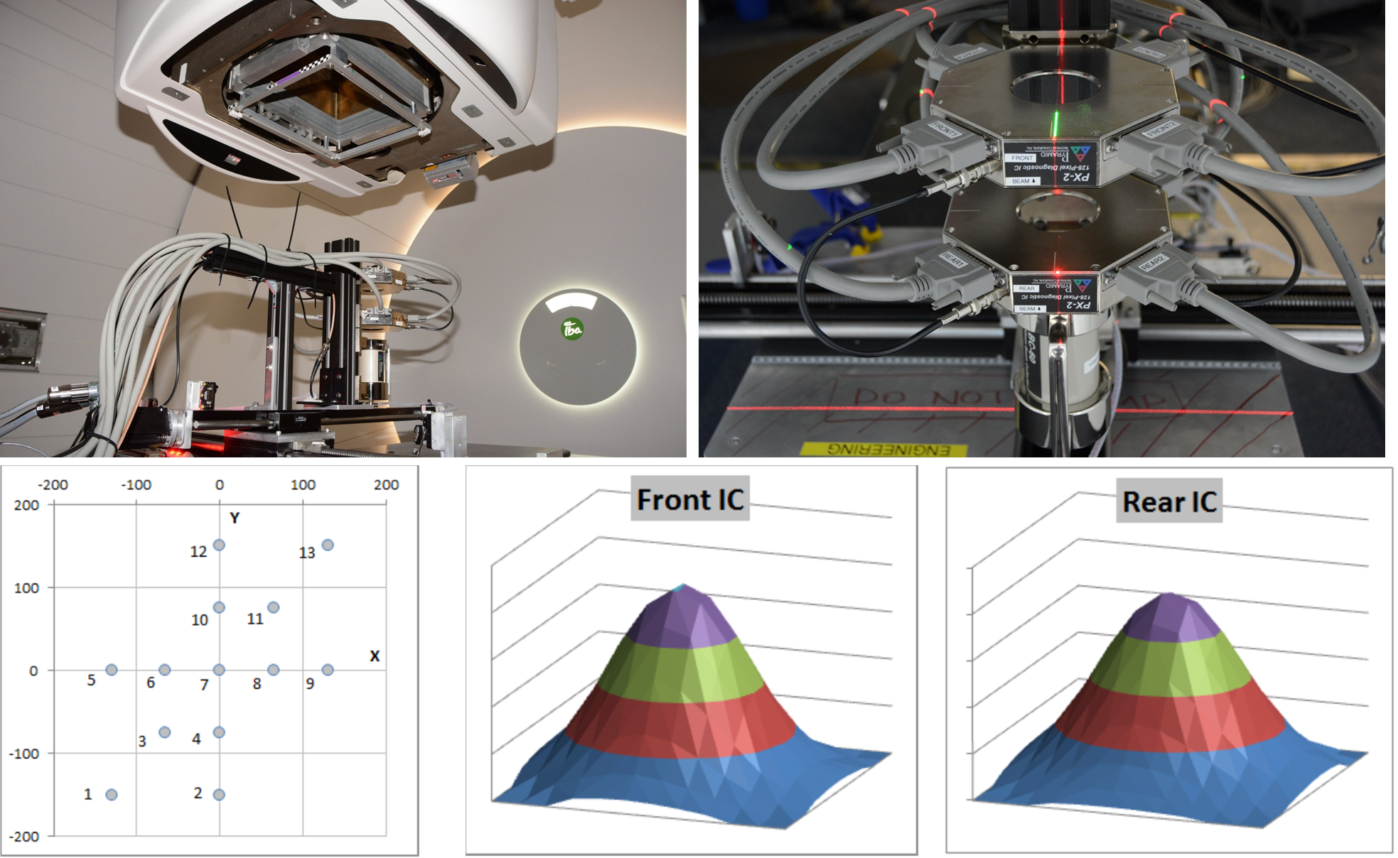
The prototype system comprising a pair of 128-pixel ion chambers and a 60mm diameter BC-60 (since replaced by the BC-75) beam collector mounted on an X-Y motion stage was set up in room 2 of the Francis H. Burr Proton Beam Therapy Center at Massachusetts General Hospital. It was mounted on the patient couch and aligned to the room laser system by eye. The prototype did not have a rotation motion, so measurements were made with the gantry set at 0 degrees. A map comprising 1 Gp dose spots over the scan field was used. At each spot the stage was moved to the nominal spot position and the images from the two ion chambers and the charge delivered to the beam collector were recorded.
A typical X-ray target bead is too small to resolve on the isocenter diagnostics ion chambers. However using a 10mm aperture in a disk placed in the X-ray imager beam path gave a clear “peak” and showed that it will be possible to align the isocenter diagnostics to the imager reference frame to better than 0.5 mm.
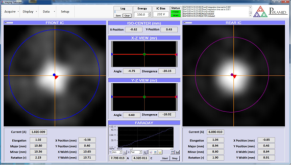
Test map pattern and typical reconstructed beam spots from the isocenter diagnostics ICs. The spots were nearly circularly symmetric with negligible ellipse rotation.
The beam collector gave good agreement with the target dose over the full scan field with an average reading of 1.028 Gp. A slight fall off at the maximum beam deflection is due to the trajectory angle combined with use of a 60 mm beam collector.
Beam width showed good consistency over the scan field, and there was a small positive divergence in both axes.
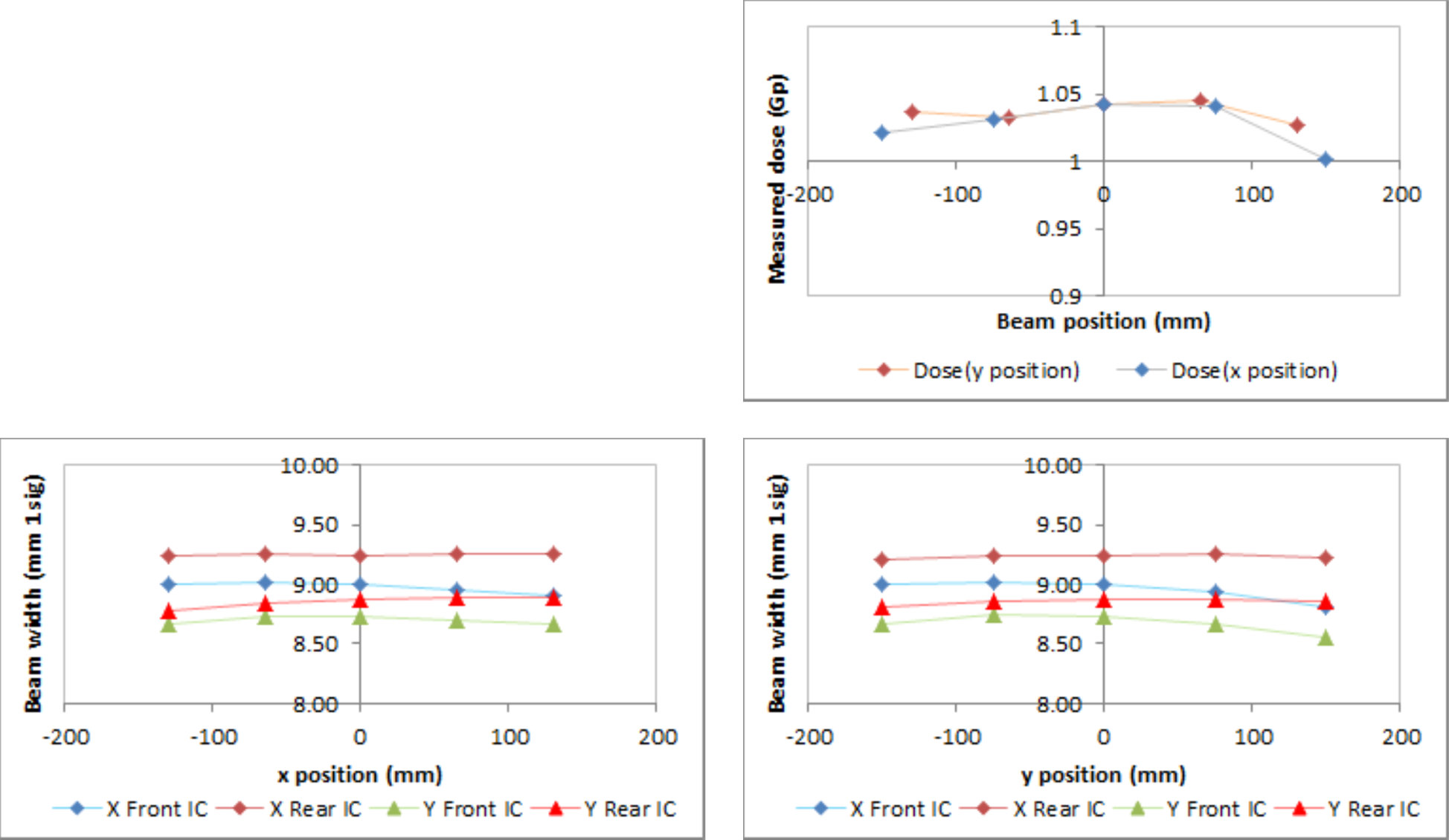
The nominal map spot positions were confirmed, when corrected for the alignment offset at 0,0. Beam trajectory angle was as expected for the y direction (gantry magnet dispersion direction and second scan magnet direction), but less than expected for the x direction.
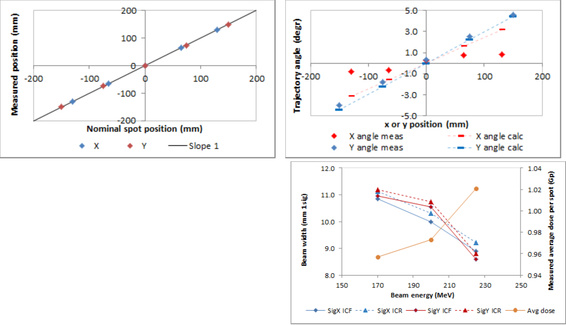
Measurements of dose and beam width at three different energies suggest that a noticeable fraction of the beam is not stopped in the beam collector as the width increases at lower energy. This will be addressed by substituting the larger diameter BC-100 collector type.
Conclusions and further work
In this initial study we have shown that an isocenter diagnostic system can quickly provide key beam data suitable for commissioning and machine QA. The system is being developed further to add energy and gantry angle validation. We are now investigating how the equipment and the data it produces can be introduced to existing QA practices [8].
References
[1] Poster P056, PTCOG 53
[2] B.Clasie et al, Phys. Med. Biol. 57(5) (2012) 1147
[3] L.Grevillot et al., Phys. Med. Biol. 56 (2011) 5203
[4] H.Kooy et al., “QA for Scanned Beams”, PTCOG 48 oral presentation
[5] N.Sahoo, “Quality Assurance Implementation in Proton Therapy Centers”, AAPM 2013
[6] KW Jee et al., PTCOG 51
[7] B. Gottschalk, http://users.physics.harvard.edu/~gottschalk/
[8] HM Lu, “Proton Therapy Operations and Physics QA at MGH, AAPM 2013